Inductor

Active Publication Date: 2012-07-05
CYNTEC
View PDF3 Cites 4 Cited by
  • Summary
  • Abstract
  • Description
  • Claims
  • Application Information

AI Technical Summary

Benefits of technology

[0014]As mentioned in the above, since the invention embeds the conducting wire into the core, the total height can be reduced effectively when the inductor is integrated with an IC chip by system-in-package technology. Accordingly, the electroni

Problems solved by technology

Thus, if the inductance has to be kept in a specific value, the total height of the conventional ind

Method used


Image

  • Inductor
  • Inductor
  • Inductor

Examples


Example

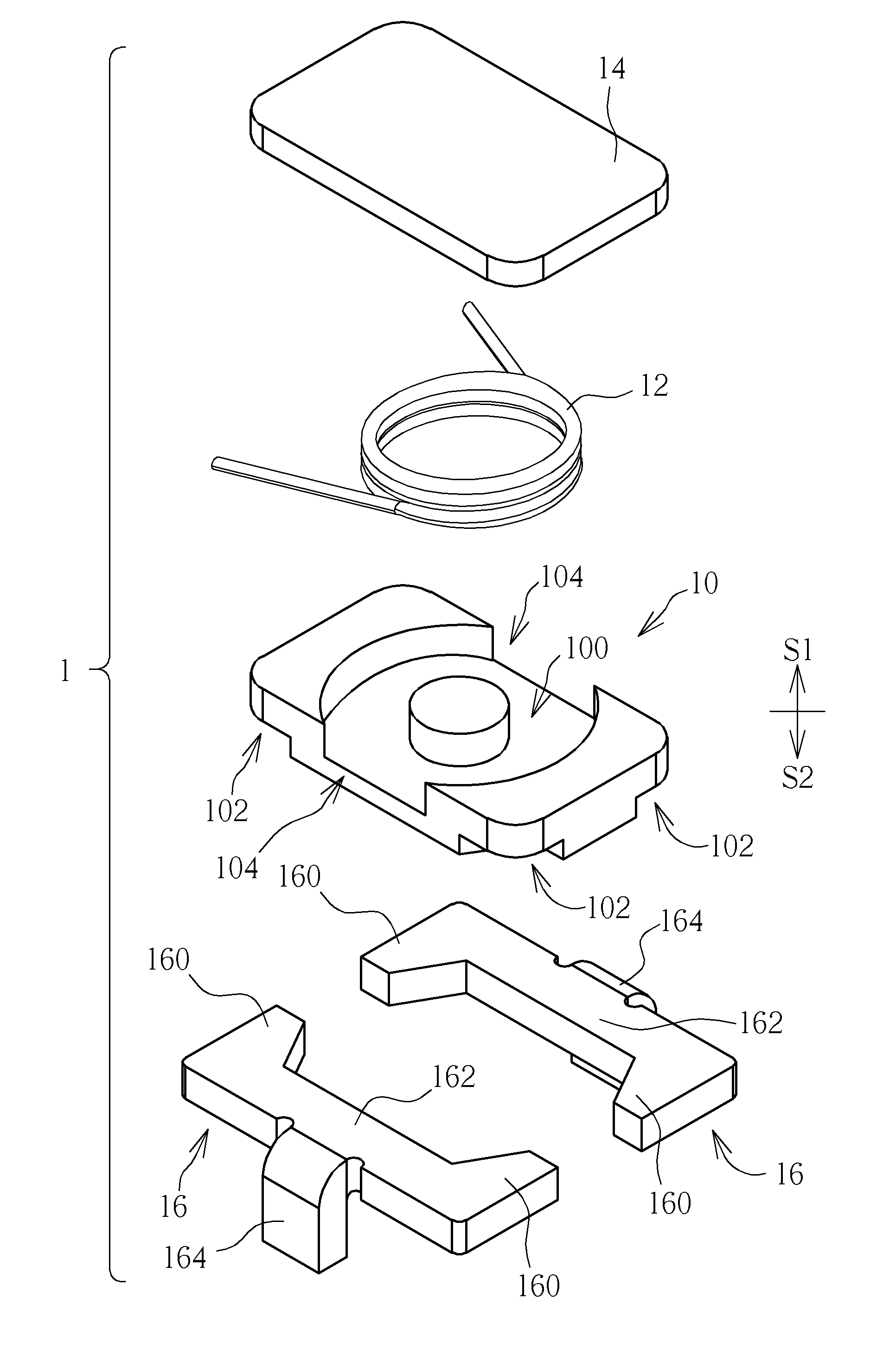
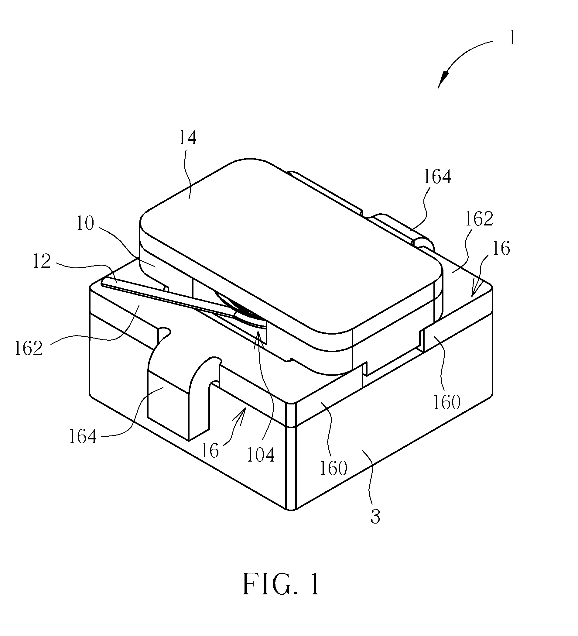
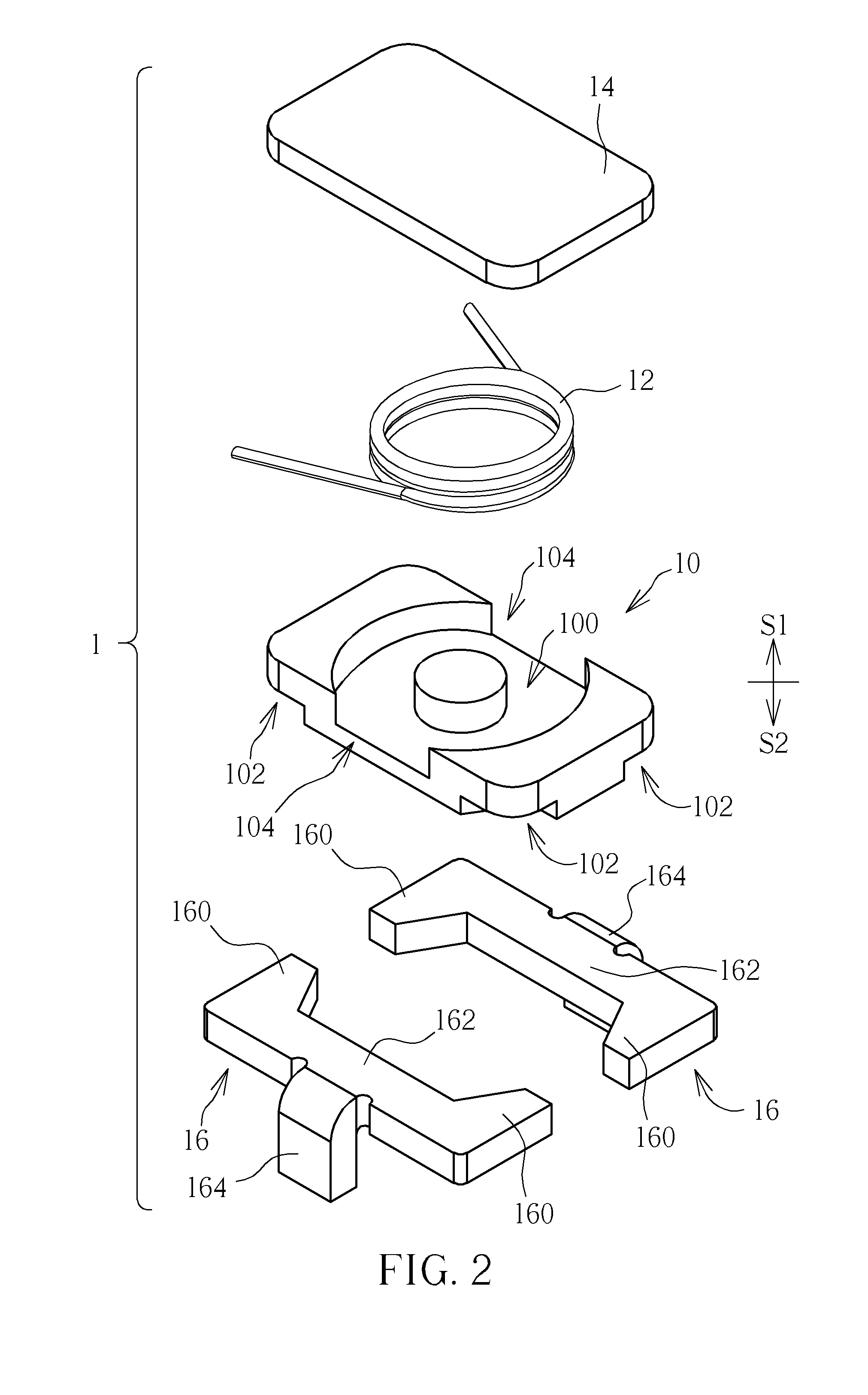
[0027]Referring to FIGS. 1 to 3, FIG. 1 is a schematic diagram illustrating an assembly of an inductor 1 and an IC chip package structure 3 according to one embodiment of the invention, FIG. 2 is an exploded view illustrating the inductor 1 shown in FIG. 1, and FIG. 3 is a front view illustrating the inductor 1 shown in FIG. 1. As shown in FIGS. 1 to 3, the inductor 1 comprises a first core 10, a conducting wire 12, a second core 14 and two first lead frames 16. The first core 10 or the second core 14 may be made of iron powder, ferrite, permanent magnet or other magnetic materials. The shape of the first core 10 or the second core 14 is not limited to rectangular as shown in the figures and may be designed in other shapes, such as circular, oval-shaped, polygonal, and soon, according to practical applications. The conducting wire 12 maybe a wire-wound coil wound by copper wire.

[0028]As shown in FIG. 2, an accommodating space 100 is formed on a first side S1 of the first core 10 and...


PUM


Abstract

An inductor includes a first core, a conducting wire, a second core and a first lead frame. There is an accommodating space formed on a first side of the first core and there is a recess portion formed on a second side of the first core, wherein the first side is opposite to the second side. The first core has a first height. The conducting wire is disposed in the accommodating space. The second core is disposed on the first side of the first core and covers the accommodating space. The first lead frame has an embedded portion embedded in the recess portion. The embedded portion has a second height. After embedding the embedded portion in the recess portion of the first core, a total height of the embedded portion and the first core is smaller than the sum of the first height and the second height.

Description

BACKGROUND OF THE INVENTION[0001]1. Field of the Invention[0002]The invention relates to an inductor and, more particularly, to an inductor adapted to be integrated with an integrated circuit (IC) chip by system-in-package (SIP) technology.[0003]2. Description of the Prior Art[0004]An inductor is a passive electrical component that can store energy in a magnetic field created by the electric current passing through it. An inductor's ability to store magnetic energy is measured by its inductance. Typically an inductor is a conducting wire shaped as a coil, the loops helping to create a strong magnetic field inside the coil due to Faraday's Law of Induction. Inductance is an effect resulting from the magnetic field that forms around a current-carrying conductor which tends to resist changes in the current. The number of loops, the size of each loop, and the material it is wrapped around all affect the inductance. For example, the magnetic flux linking these turns can be increased by c...

Claims


Application Information

Patent Timeline
IPC IPC(8): H01F17/00
CPCH01F17/043H01F3/08H01F37/00H01F27/292H01F27/02H01F5/00H01F27/24H01F27/2828H01F27/29H05K1/18H05K7/026
Inventor WU, TSUNG-CHAN
Owner CYNTEC
Why Eureka
Try Eureka