Display panel

A technology of display panel and backlight surface, applied in semiconductor devices, electrical components, circuits, etc., to improve display effect and reduce chromaticity difference

Pending Publication Date: 2022-07-01
GUANGZHOU CHINA STAR OPTOELECTRONICS SEMICON DISPLAY TECH CO LTD
View PDF0 Cites 0 Cited by
  • Summary
  • Abstract
  • Description
  • Claims
  • Application Information

AI Technical Summary

Problems solved by technology

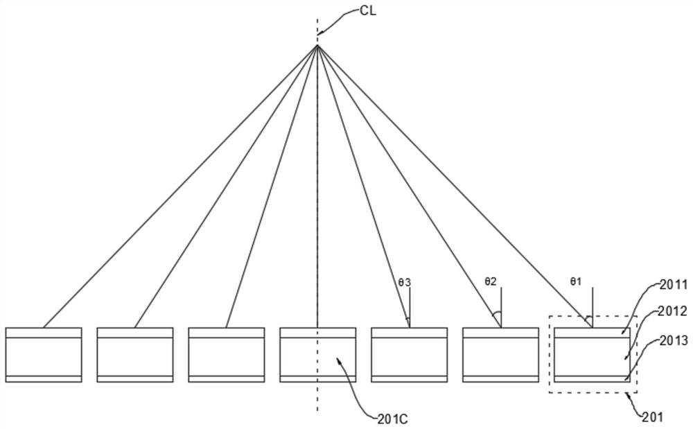
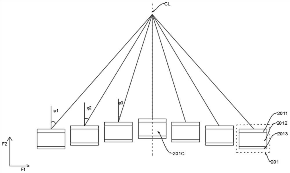
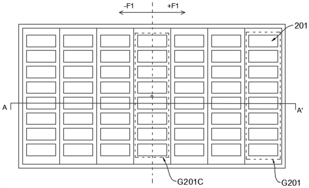
[0004] The embodiment of the present application provides a display panel, which can solve the problem of chromaticity difference caused by viewing the display panel at different angles by setting an adjustment layer, and improve user experience

Method used


Image

  • Display panel
  • Display panel
  • Display panel

Examples


Embodiment Construction

[0040] The technical solutions in the embodiments of the present application will be clearly and completely described below with reference to the drawings in the embodiments of the present application. Obviously, the described embodiments are only a part of the embodiments of the present application, rather than all the embodiments. Based on the embodiments in the present application, all other embodiments obtained by those skilled in the art without creative work fall within the protection scope of the present application.

[0041] Embodiments of the present application provide a display panel and a mobile terminal. Each of them will be described in detail below. It should be noted that the description order of the following embodiments is not intended to limit the preferred order of the embodiments. In addition, in the description of this application, the term "including" means "including but not limited to". The terms first, second, third, etc. are used merely as designat...


PUM


Abstract

The embodiment of the invention discloses a display panel, the display panel comprises a light-emitting layer and an adjusting layer, the light-emitting layer comprises a plurality of light-emitting unit groups arranged along a first direction, each light-emitting unit group comprises at least one light-emitting unit, and the plurality of light-emitting unit groups comprise a visual center unit group; the adjusting layer comprises a plurality of adjusting unit groups corresponding to the light-emitting unit groups; the adjusting layer is arranged on one side of the light-emitting layer, when the adjusting layer is arranged on one side of the backlight face of the light-emitting layer, different adjusting unit sets can be set to have different thicknesses or have different inclination angle numbers, and when the adjusting layer is arranged on one side of the light-emitting face of the light-emitting layer, the adjusting unit sets can be set to have different inclination angle numbers. Different adjusting unit groups can be set to have different refractive indexes, so that the chromaticity difference of the electroluminescent display device caused by the difference of viewing angles of a user is reduced, and the display effect of the display panel is further improved.

Description

technical field [0001] The present application relates to the field of display technology, and in particular, to a display panel. Background technique [0002] In the organic electroluminescent display panel, a top-emitting device structure is usually adopted, and the structure is a total reflection anode, an organic light-emitting layer and a semi-reflective cathode arranged in an overlapping manner, and the structure makes the light-emitting device structure form a microcavity. [0003] When the observation point of the human eye is determined, the observation angle of the human eye is different for the light emitted by the light-emitting device at different positions. The farther the light-emitting device is from the observation point of the human eye, the light emitted by the light-emitting device observed by the human eye corresponds to The larger the angle between the normals of the light-emitting devices is, the chromaticity of the multiple light-emitting devices obse...

Claims


Application Information

Patent Timeline
Patent Type & Authority Applications(China)
IPC IPC(8): H01L51/52H01L27/32
CPCH10K59/12H10K50/85H10K50/86
Inventor 欧建兵
Owner GUANGZHOU CHINA STAR OPTOELECTRONICS SEMICON DISPLAY TECH CO LTD
Why Eureka
Try Eureka