
Rotary pile leg mechanism

A technology of pile legs and pile fixing frame, which is applied in sheet pile wall, foundation structure engineering, construction, etc., can solve the problem of tall structure, unable to meet the loading requirements of ships crossing the sea, and segmented pile leg assembly cannot be completed manually, etc. problems, to achieve the effect of ensuring work safety

Active Publication Date: 2022-07-05
ARMY ENG UNIV OF PLA +1
View PDF14 Cites 0 Cited by
  • Summary
  • Abstract
  • Description
  • Claims
  • Application Information

AI Technical Summary

Problems solved by technology

[0002] When the elevated trestle module is transported across the sea, other transport ships are usually required to transport it across the sea. Generally, the pile legs of the elevated trestle are arranged vertically and have a tall structure, which cannot be folded, cannot be loaded on the transport ship, and cannot meet the loading requirements of the transport ship across the sea. With the existing segmented pile leg structure, the elevated trestle module does not have the conditions to be equipped with hoisting machinery, and the assembly of the segmented pile legs cannot be completed manually, which brings unavoidable problems to the elevated trestle erection operation

Method used


Image

  • Rotary pile leg mechanism
  • Rotary pile leg mechanism
  • Rotary pile leg mechanism

Examples


Embodiment Construction

[0018] The implementation of the technical solution will be further described in detail below with reference to the accompanying drawings. The following examples are only used to illustrate the technical solutions of the present invention more clearly, and cannot be used to limit the protection scope of the present invention.

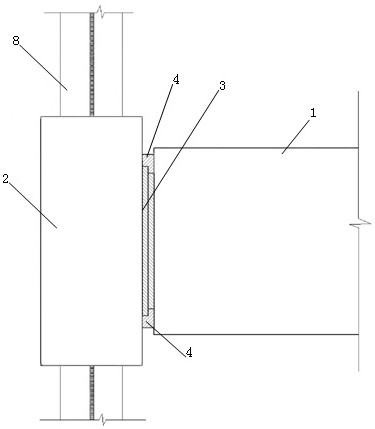
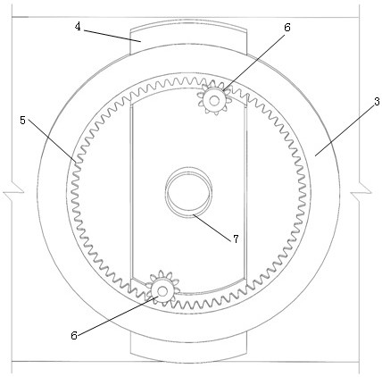
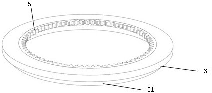
[0019] like Figure 1~2 One embodiment shown: a rotating leg mechanism, comprising: a pile fixing frame 2, a fixed tenon ring 3, a rotating bracket 4 and a rotating fixed shaft 7; the pile fixing frame 2 is connected to the platform by connecting the rotating fixed shaft 7 1. Rotational connection, the pile fixing frame 2 is fixed with the rotating bracket 4, the pile fixing frame 2 is connected to the pile legs 8, and the pile fixing frame 2 is connected to the platform 1 through the connection of the rotating bracket 4 and the fixed tenon ring 3. Described rotating support 4 comprises: inner socket ring 42, outer socket ring 43 and socket connecting ...


PUM


Abstract

The invention discloses a rotating pile leg mechanism which comprises a pile fixing frame, a fixing tenon ring, a rotating support and a rotating fixing shaft. A pile leg is installed in the pile fixing frame, the pile fixing frame is connected with the platform through a rotating fixing shaft, the pile fixing frame is connected with the side face of the platform through a rotating support and a fixing tenon ring, and the rotating support comprises an inner mortise ring, an outer mortise ring and a mortise groove connecting plate; the middle of the mortise groove connecting plate is rotationally connected with the rotary fixing shaft, the two ends of the mortise groove connecting plate are connected with the inner mortise ring, the outer side of the inner mortise ring is connected with the outer mortise ring, a mortise ring groove with the T-shaped section is formed between the inner mortise ring and the outer mortise ring, one side of the fixed tenon ring is slidably connected into the mortise ring groove, and the other side of the fixed tenon ring is fixed to the platform. According to the folding type rotating pile leg driving and fixing mechanism, the pile leg such as a thin and long structure can be loaded in a folding mode, the pile leg is placed parallel to a platform in the transportation state, and the pile leg is perpendicular to the platform and becomes a supporting leg of the platform in the working state.

Description

technical field [0001] The invention discloses a rotary leg mechanism, which relates to the technical field of elevated trestle bridges. Background technique [0002] When the viaduct module is transported across the sea, other transport ships are usually required to transport across the sea. Generally, the pile legs of the viaduct are arranged vertically, and the structure is tall and cannot be folded. With the existing segmented leg structure, the module of the elevated trestle does not have the conditions for hoisting machinery, and the assembly of the segmented legs cannot be done manually, which brings unavoidable problems to the erection of the elevated trestle. SUMMARY OF THE INVENTION [0003] Aiming at the defects in the above-mentioned background technology, the present invention provides a rotating leg mechanism, which solves the problems of loading, transportation and erection operations in the cross-sea transportation of the viaduct trestle module. [0004] I...

Claims


Application Information

Patent Timeline
Patent Type & Authority Applications(China)
IPC IPC(8): E02D27/12E02D27/42E02D27/52E02D5/24
CPCE02D27/12E02D27/42E02D27/52E02D5/24Y02E10/727
Inventor 邵飞徐倩白林越李志刚孙永岗谢兴坤王浩何立翔焦经纬袁嘉欣
Owner ARMY ENG UNIV OF PLA
Learn More