
MEMS device with increased tilting range

Inactive Publication Date: 2014-02-06
JDS UNIPHASE CORP
View PDF2 Cites 0 Cited by
  • Summary
  • Abstract
  • Description
  • Claims
  • Application Information

AI Technical Summary

Benefits of technology

The invention improves the stiffness of a pivoting member by adding a hot electrode to the surface of the substrate. This makes the pivoting member more robust and able to withstand tilting without losing its effectiveness.

Problems solved by technology

The first is to enable precise and controllable orientations of the micro mirror, which stems from the fact that imprecise mirror tilt angles might cause the light signals to miss the small fiber cores of the various output optical fibers in the switch causing loss of data during switching.
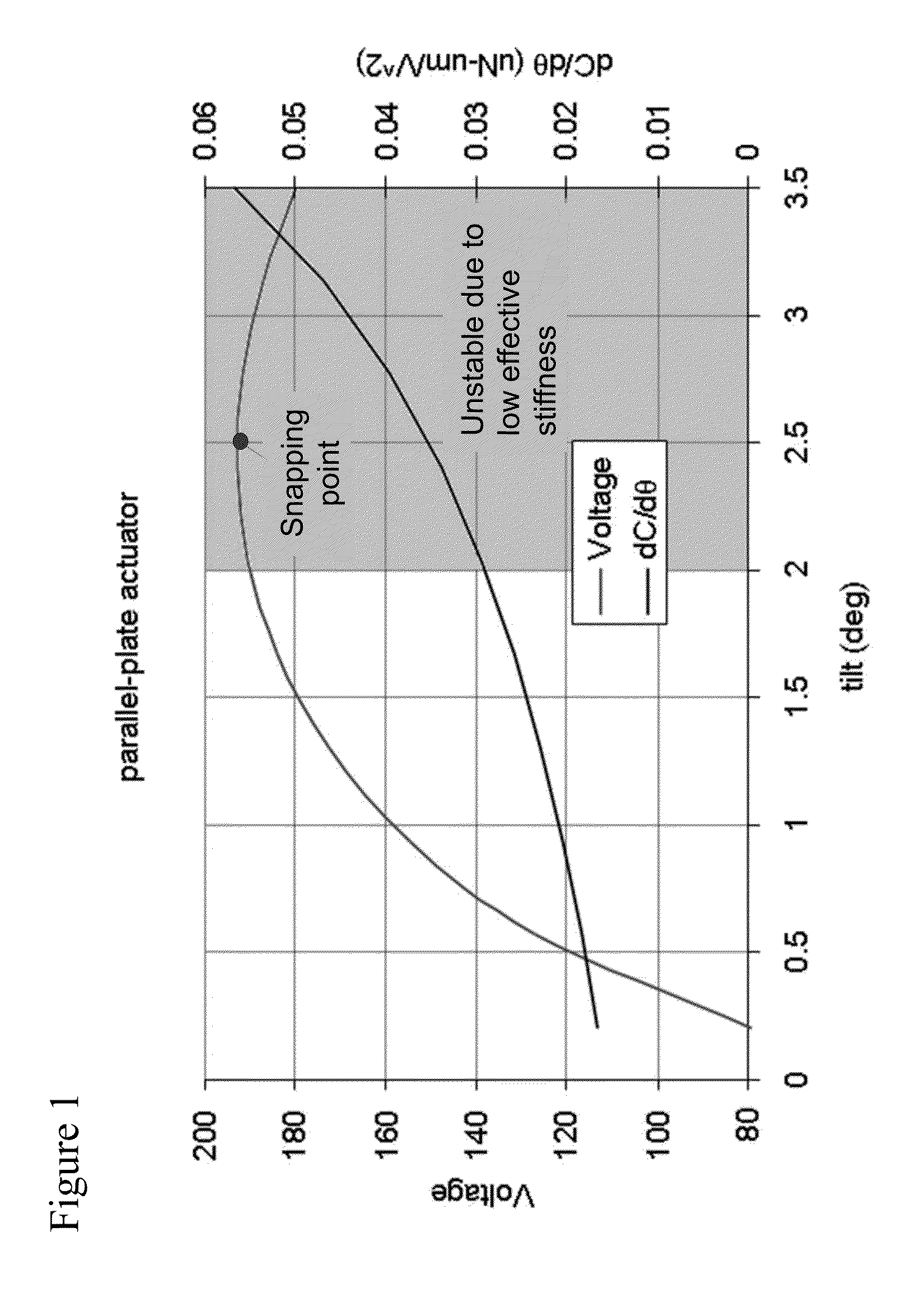
However, their usable angle range is severely limited by the well-known “snapping” phenomenon, as shown in FIG. 1.
The root cause of the snapping is that the electrical driving torque on the mirror with a constant voltage
Approaching the snap point, the effective stiffness become so small that the mirror tilt is very sensitive to voltage variation and external turbulence.
Depending on the stability and control resolution requirements of the application, a large portion of the tilt range near the snapping point become unusable.

Method used


Image

  • MEMS device with increased tilting range
  • MEMS device with increased tilting range
  • MEMS device with increased tilting range

Examples


Embodiment Construction

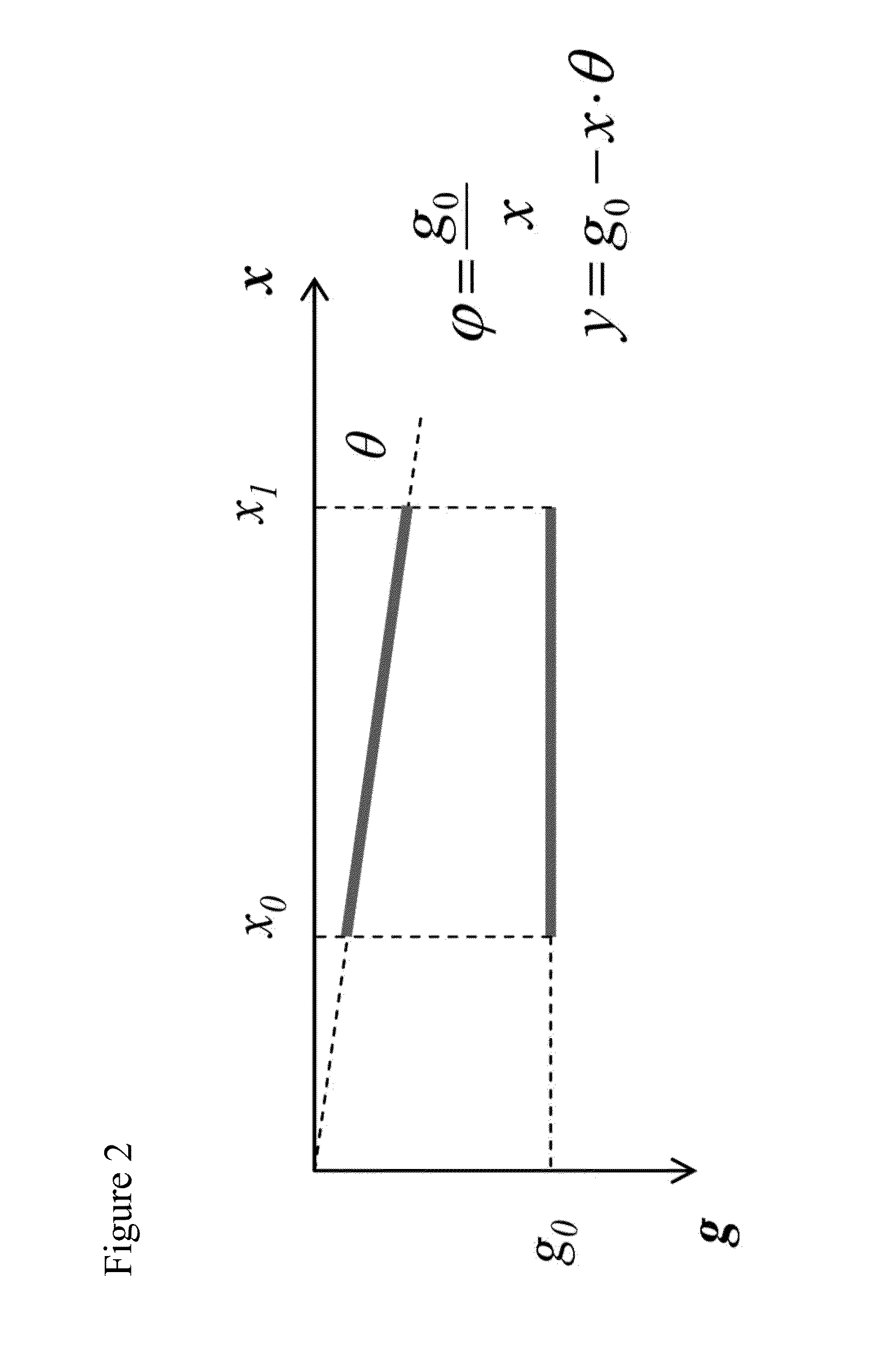
[0024]The design parameter definitions for an angular parallel plate actuator are illustrated in FIG. 2, in which g0 is the original distance between a hot electrode on the substrate and a ground electrode on pivoting mirror, x is the distance along the ground electrode of the pivoting mirror, and θ is the angle of the mirror between horizontal and the current position.

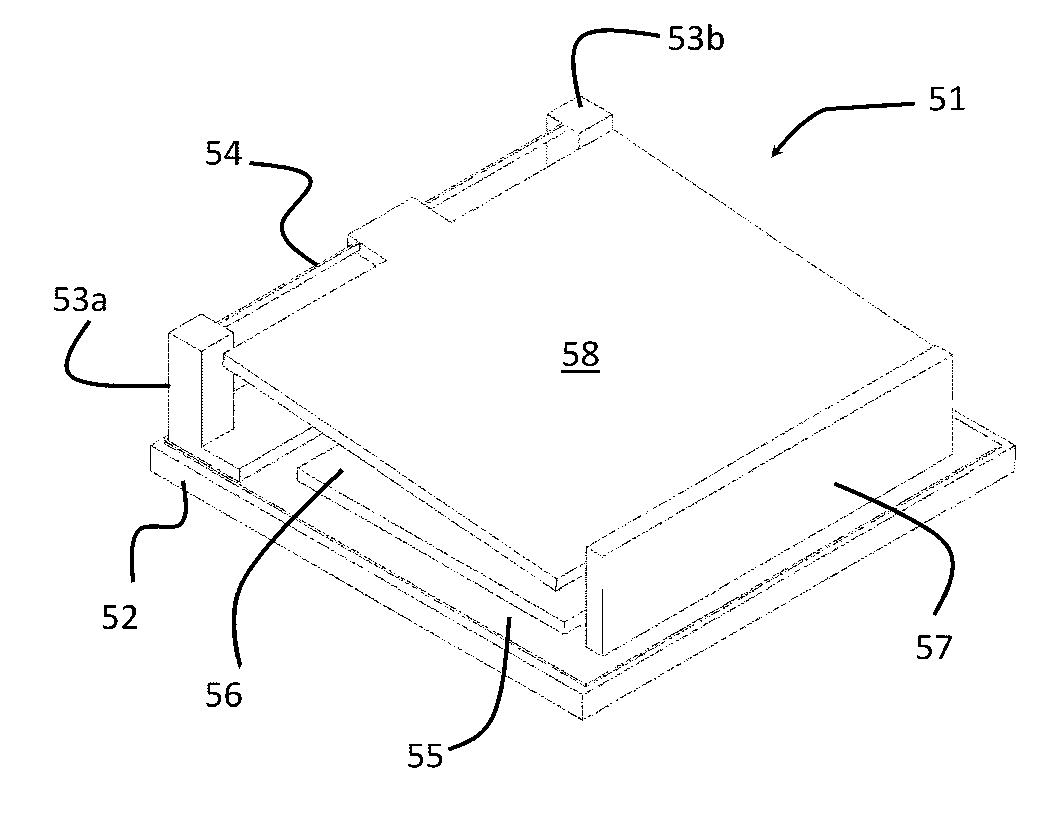
[0025]According to the present invention, a micro-electro-mechanical (MEMs) device having a higher effective stiffness is illustrated in FIGS. 3, 4 and 5. Any form of tilting MEMs device including a pivoting member acting as a ground electrode pivotally mounted over a substrate via a hinge and actuated by a hot electrode below one side thereof, can be used as the basis for the present invention, and the following embodiments are only meant to be exemplary. In particular, any form of hinge structure can be used, including those disclosed in U.S. Pat. No. 6,934,439, which is incorporated herein by reference.

[0026]With p...


PUM


Abstract

A micro-electro-mechanical (MEMs) devices including a compound hot electrode, which increases the tilting range of the MEMs device. A substantially vertical hot electrode is mounted adjacent to the end or the sides of a pivoting ground electrode, formed of the underside of a pivoting mirror, and combine with a conventional horizontal hot electrode to make up the compound hot electrode.

Description

TECHNICAL FIELD[0001]The present invention relates to a pivoting MEMs device, and in particular to a pivoting MEMs device with a compound ground electrode for eliminating unwanted snapping.BACKGROUND OF THE INVENTION[0002]The micro electro-mechanical (MEMs) device of the present invention is an electrostatically actuated tilting micro mirror with a torsional spring used for optical switching. When used in fiber optic networks, the MEMs mirrors redirect light signals carrying data from one optical fiber to another in order to reach a desired destination.[0003]In optical switching applications, a micro mirror needs to satisfy three requirements. The first is to enable precise and controllable orientations of the micro mirror, which stems from the fact that imprecise mirror tilt angles might cause the light signals to miss the small fiber cores of the various output optical fibers in the switch causing loss of data during switching. In particular, when the distance between the micro mi...

Claims


Application Information

Patent Timeline
IPC IPC(8): H02N1/00
CPCB81B3/0043G02B6/357G02B26/0841B81B2201/042
Inventor JIN, WENLIN
Owner JDS UNIPHASE CORP
Learn More