Railway clamp

A rail clip and rail technology, applied in the field of rail clips, can solve the problems of small differences in rail manufacturing tolerances, lateral displacement of rails, and the ability to reduce longitudinal sliding of rails.

Inactive Publication Date: 2007-01-10
OTIS ELEVATOR CO
View PDF4 Cites 0 Cited by
  • Summary
  • Abstract
  • Description
  • Claims
  • Application Information

AI Technical Summary

Problems solved by technology

[0005] The disadvantage of flexible track clamps is that they usually do not meet the code requirements for protection against earthquakes
Also, many so-called flexible track clamps, while allowing for some longitudinal displacement, are not suitable for use where there is rust on the underside of the track or where there are any slight differences in track manufacturing tolerances that could result in a Lateral displacement of the track under the clip
Any such change in lateral displacement may significantly increase the holding force of the track clamps on the track, thereby reducing the ability of the track to slide longitudinally

Method used


Image

  • Railway clamp
  • Railway clamp
  • Railway clamp

Examples


Embodiment Construction

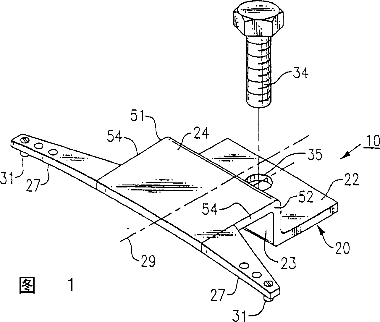
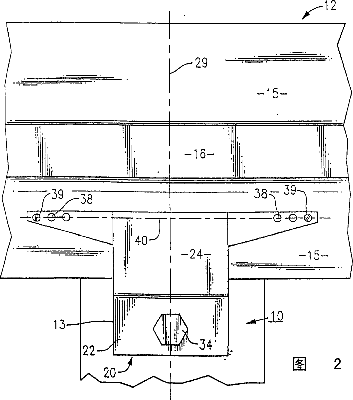
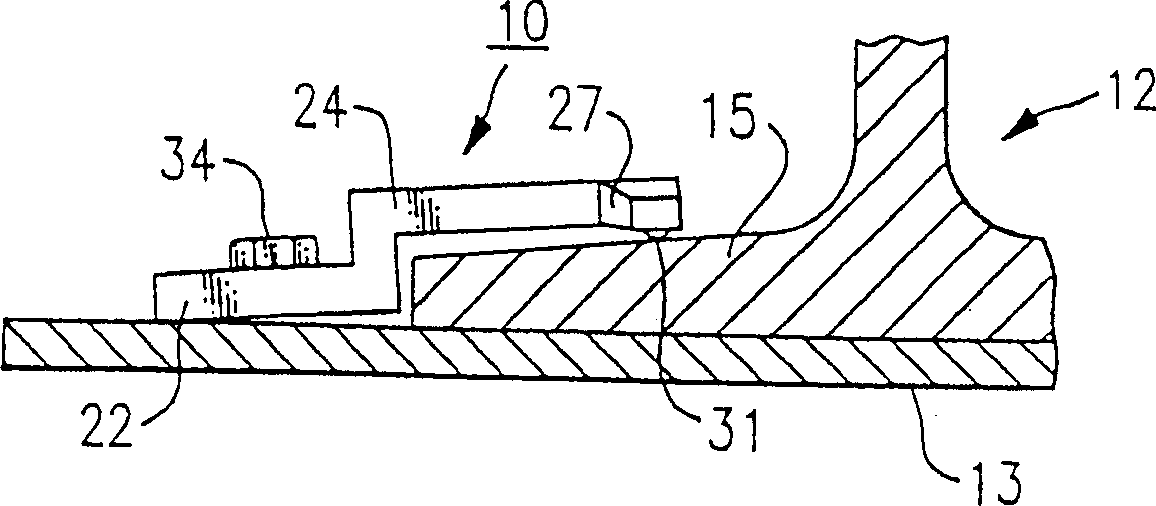
[0028] Referring initially to FIGS. 1 and 2 , there is shown a track clamp, generally designated 10 , which is ideally adapted to secure an elevator guide rail section 12 to a bottom support frame 13 . As previously mentioned, a typical guide rail currently in widespread use in many elevator systems has a T-shaped cross-sectional configuration and includes a bottom flange 15 and a web or riser 16 centered longitudinally along the flange. The elevator guide rail sections are assembled vertically aligned end-to-end. As is well known, elevator cabs and associated counterweight units are respectively mounted for free movement along a pair of spaced apart tracks on rollers or guide plates which straddle along the riser portions of each track.

[0029] Each track segment is connected to multiple support frames with a number of track clips. As will be explained in more detail below, each track clip initially exhibits a linear response that is sufficiently flexible to allow for longi...


PUM


Abstract

A rail clip that is generally symmetrical about a central axis. The clip has an L-shaped base section having a horizontal leg that is securable to a support member upon which the rail rest and a vertical leg that extends upwardly from the base adjacent to the rail. An arm extends outwardly over the rail from the vertical leg of the base section and an elongated beam is mounted in the distal end of the arm that extends outwardly to either side of the arm so that beams run longitudinally along the rail. A contact pad is carried on both ends of the beam which normally rest in holding contact against the rail. As the rail is displaced upwardly in reference to the arm, second contact points are established to progressively stiffen the clip.

Description

technical field [0001] The present invention relates generally to track clamps, and more particularly to track clamps ideally suited for securing guide rails of elevator systems to base support frames. Background technique [0002] In a traction elevator system, the elevator cabin is connected to a counterweight unit by means of hoist ropes and a system of tackle or pulleys. The elevator car and the counterweight unit are each typically mounted on a pair of vertically extending rails, which are arranged on rollers or guide plates so as to straddle the rails. The guide rails generally have a T-shaped cross-section, and they are typically erected in 16-foot sections and attached by support frames to the building in which the elevator system is installed. [0003] During assembly, the bottom flange of the T-shaped vertical section of the guide rail is connected to the support frame by means of track clamps, so that the riser or web section of each track can be directed inwardl...

Claims


Application Information

Patent Timeline
Patent Type & Authority Patents(China)
IPC IPC(8): B66B7/02E01B9/30E01B9/66
CPCE01B9/66B66B7/024B66B7/02
Inventor B·G·特拉克托文科
Owner OTIS ELEVATOR CO
Why Eureka
Try Eureka