Steel-concrete combined connection structure in concrete tension state

A combined connection and concrete technology, applied in construction, bridge construction, bridges, etc., can solve the problems of partial renovation of composite beams, complex on-site construction, high cost and uneconomical problems, and achieve superior interface shear bearing capacity, simple construction, The effect of increasing ductile energy dissipation capacity

Pending Publication Date: 2020-08-25
HUNAN UNIV OF SCI & TECH +1
View PDF1 Cites 0 Cited by
  • Summary
  • Abstract
  • Description
  • Claims
  • Application Information

AI Technical Summary

Problems solved by technology

[0004] (1) The on-site construction is complicated, the workload is heavy, the construction period is long, and it is difficult to partially renovate the composite beam in the future;
[0005] (2) Some technologies will cause local stress concentration, and necessary structural measures need to be taken to improve the stress concentration problem, resulting in complex design;
[0006] (3) The cost is high and uneconomical, and the effect is not ideal. It is often necessary to use several methods at the same time to solve the problem of the negative moment area of ​​the composite beam

Method used


Image

  • Steel-concrete combined connection structure in concrete tension state
  • Steel-concrete combined connection structure in concrete tension state
  • Steel-concrete combined connection structure in concrete tension state

Examples


Embodiment 1

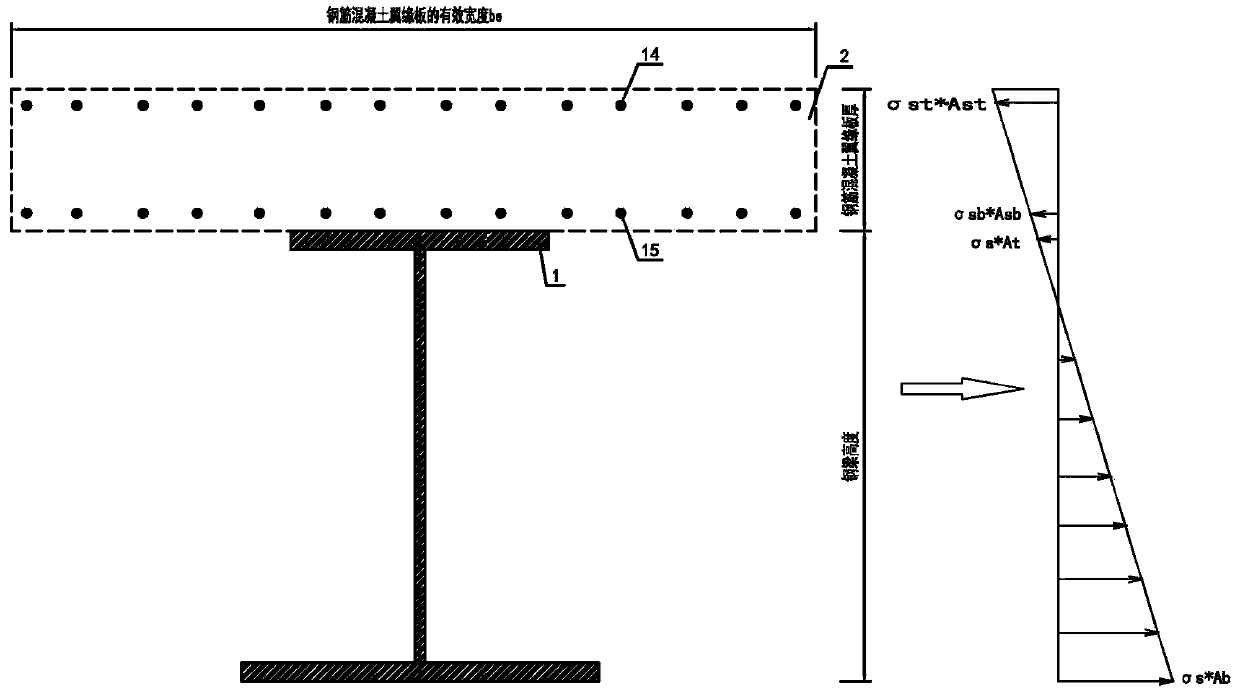
[0060] When the upper flange of the steel beam in the negative moment zone adopts the stud shear connector with constrained structure, when the concrete flange plate in the composite section is basically under the axial tension or the tension-bend composite tension state, the concrete is always under the full-section tension state, according to the single stud 3 shear triangular truss balance unit, it can be known that when the whole concrete is in a tension state, it is impossible to form an oblique concrete compression bar in the concrete flange plate like the concrete in the compression zone, and the stud 3 The shear resistance requires the oblique component force of the longitudinal and transverse steel bars at the top and bottom of the flange plate to provide the slash tension in the shear triangle truss balance unit of the stud 3 to balance the longitudinal shear force of the stud 3. Therefore, in order to balance the restraint For the longitudinal shear force of the cons...

Embodiment 2

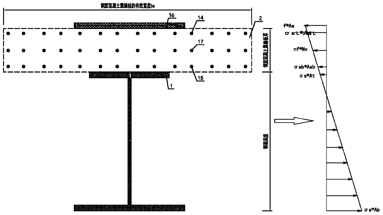
[0064] A steel plate for resisting tensile stress to compensate for strength and stiffness is directly added at the maximum tensile stress of the concrete flange plate section, that is, a tensile steel plate 16 is added on the top of the steel beam concrete flange plate 2, and the additional tensile steel plate at this position directly Bear the section tensile stress of the concrete flange plate at this position. In the negative moment zone of the continuous composite beam, the steel-concrete composite slab is formed by the shear connector 3 with restraint structure and the additional steel plate on the top of the concrete flange plate 2 of the steel beam. The shear force transmission capacity of the constructed stud 3 shear connectors is realized. Due to the use of the stud 3 shear connector with constrained structure, the shear connector can effectively avoid local pressure splitting damage, has strong shear stiffness, and still has a good shear force when the shear force e...

Embodiment 3

[0067] In the first and second embodiments above, the two connection methods are adopted simultaneously, that is, an additional oblique reinforcement 17 and an additional transverse reinforcement 18 to resist the shear force of the stud 3 are added at the neutral axis section of the concrete flange plate section, When the concrete is in tension as a whole, the balance tie element of a single stud 3 shear triangular truss balance element (such as Figure 19 Shown) and the composite beam concrete flange plate 2 top additional tensile steel plate 16 of the composite beam concrete flange plate 2 top that directly increases the compensating composite beam strength resisting tensile stress at the maximum tensile stress of the concrete flange plate section, the typical continuous of its present invention proposes The schematic diagram of the mechanical characteristics of the composite section in the negative moment zone of the composite beam is as follows: figure 2 shown.

[0068] ...


PUM


Abstract

The invention discloses a steel-concrete combined connection structure in a concrete tension state, and provides a series of novel structure construction methods by utilizing stud shear resisting connectors with constraint structures and utilizing excellent and stable stress performance of the stud shear resisting connectors in an aspect of steel-concrete interface shear resisting rigidity. By adopting the novel structure construction method under a condition that an axis of the concrete is tensioned or bent, an adverse effect of concrete tension cracking in steel-concrete combined connectioncan be effectively reduced, and connection strength and connection rigidity of the combined connection under the condition that the axis is tensioned or bent can be simply and effectively reinforced or enhanced. For example, when the novel connecting construction method is applied to a combined beam hogging moment area, concrete in the combined beam hogging moment area can be effectively controlled and prevented from being pulled and cracked so that flexural rigidity of the composite beam hogging moment area can be reinforced or enhanced, and an engineering problem that a combined applicationdegree is low due to concrete cracking of steel-concrete combined connection in the hogging moment area is solved.

Description

technical field [0001] The invention relates to the technical field of stud shear connectors, in particular to a steel-concrete composite connection structure under concrete tension. Background technique [0002] Steel-concrete continuous composite beams will have unfavorable conditions in the negative bending moment area, such as concrete tension and steel beam compression, especially the cracking of concrete slabs, which will cause the reduction of the stiffness and durability of composite beams. Therefore, it has become a key issue in the design of continuous composite beams to adopt effective design, construction methods and treatment measures to effectively control and prevent concrete cracking in the negative moment zone. At present, the commonly used treatment methods are: preloading method, support pre-lifting method, prestressing method, reinforcement limit concrete crack width method, post-combined prestressed concrete bridge deck method, steel beam bottom plate po...

Claims


Application Information

Patent Timeline
Patent Type & Authority Applications(China)
IPC IPC(8): E01D1/00E01D101/26
CPCE01D1/00E01D2101/268
Inventor 戚菁菁曹华卜明华吕伟荣石卫华谢祖巍
Owner HUNAN UNIV OF SCI & TECH
Why Eureka
Try Eureka