
Hair drier integrated circuit capable of automatically switching states

A technology of integrated circuits and hair dryers, which can be used in devices for washing hair or scalp, clothing, hairdressing equipment, etc., and can solve problems such as increased production and R&D costs.

Pending Publication Date: 2022-07-08
广东精装照明有限公司
View PDF0 Cites 0 Cited by
  • Summary
  • Abstract
  • Description
  • Claims
  • Application Information

AI Technical Summary

Problems solved by technology

[0004] However, in the actual research and development process, the applicant found that, due to the increase in the number of heating elements compared with the number of heating elements of a traditional hair dryer, and the need for the heating power of the second heating element and the third heating element to be different from that of the first heating element , needs to be controlled separately, and at the same time, in order to provide a fast drying effect, the mode of using a large current to generate high heat through the heating element cannot be abandoned under the previous high-heating gear. Therefore, to meet the above requirements, manufacturers need to develop a hair dryer with a complex structure. Circuits, and even need to combine control chips and auxiliary circuits to drive and control each heating element. However, this also means an increase in production and R&D costs, and it is difficult to meet the needs of manufacturers.

Method used


Image

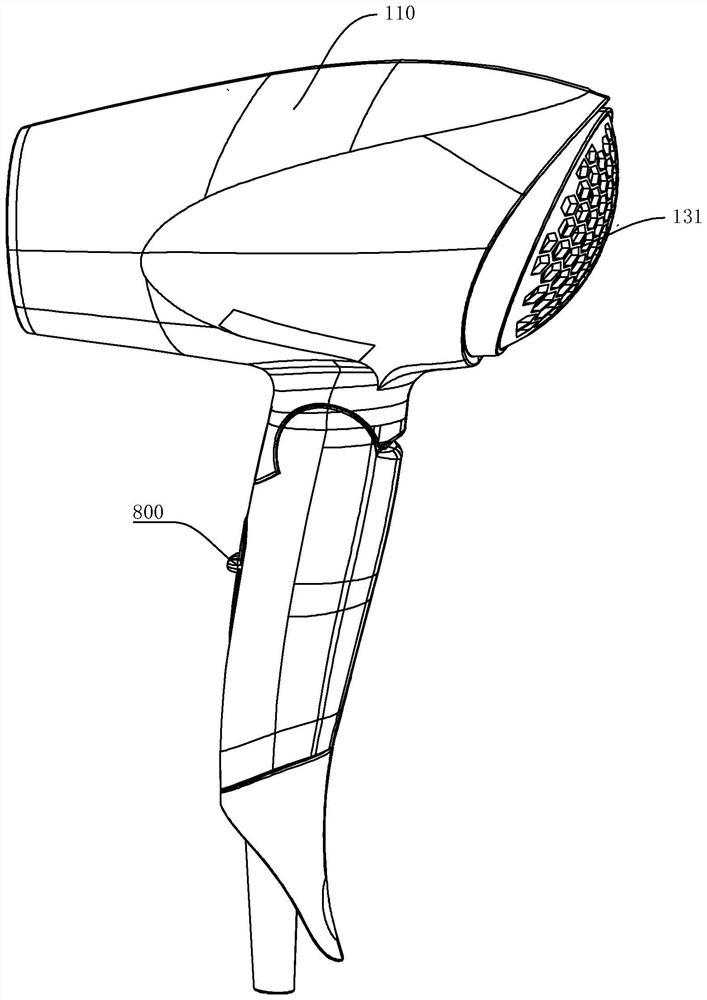
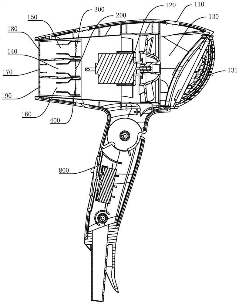
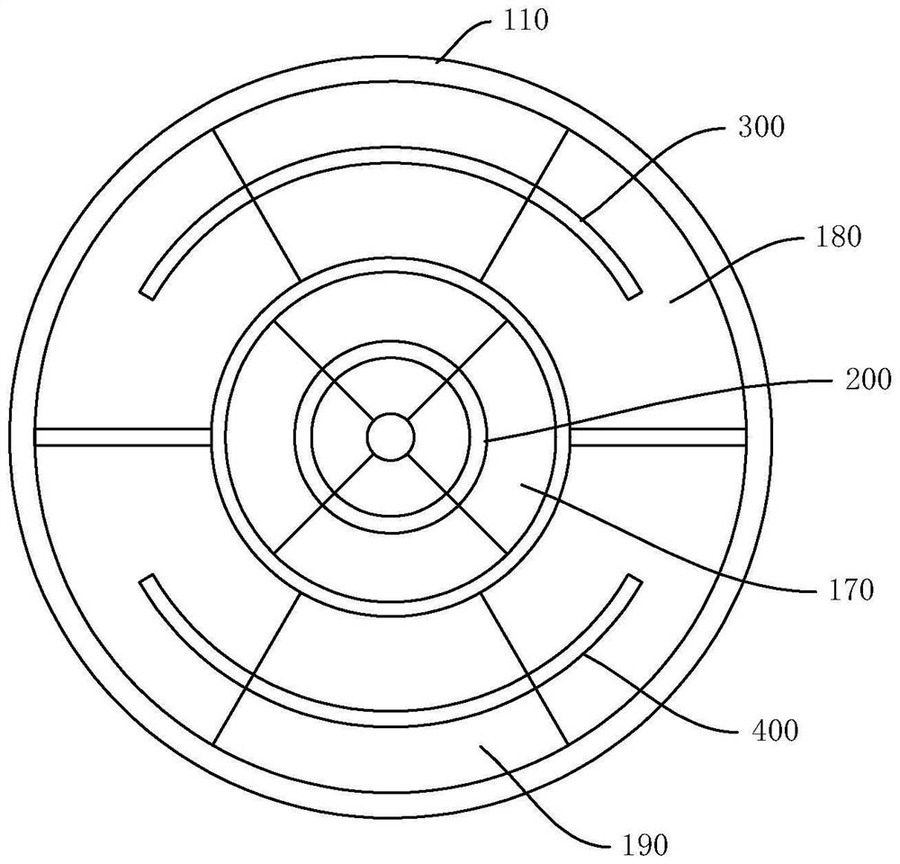
  • Hair drier integrated circuit capable of automatically switching states
  • Hair drier integrated circuit capable of automatically switching states
  • Hair drier integrated circuit capable of automatically switching states

Examples


Embodiment Construction

[0025] The following describes in detail the embodiments of the present invention, examples of which are illustrated in the accompanying drawings, wherein the same or similar reference numerals refer to the same or similar elements or elements having the same or similar functions throughout. The embodiments described below with reference to the accompanying drawings are exemplary, only used to explain the present invention, and should not be construed as a limitation of the present invention.

[0026] In the description of the present invention, it should be understood that orientation descriptions are involved, such as the terms "upper", "lower", "front", "rear", "left", "right", "vertical", "horizontal" "," "top", "bottom", "inside", "outside" and other indicated orientations or positional relationships are based on the orientations or positional relationships shown in the accompanying drawings, which are only for the convenience of describing the present invention and simpli...


PUM


Abstract

The invention discloses a blower integrated circuit capable of automatically switching states, which comprises a power supply driving module, a control module and a connection structure switching module, and is characterized in that the control module is connected with the power supply driving module so as to control the power supply driving module to adjust the magnitude of power supply current; the connection structure switching module is connected with the second heating element and the third heating element to form at least part of switching units, the switching units are connected with the first heating element in series to form at least part of series branches, and the output end of the power supply driving module is connected with the series branches to supply power to the series branches; wherein the connection structure switching module is internally provided with a current threshold value, when the power supply current is larger than the current threshold value, the connection structure switching module enables the second heating piece and the third heating piece to be connected in series, and when the power supply current is smaller than the current threshold value, the connection structure switching module enables the second heating piece and the third heating piece to be connected in parallel; the design is simple in structure and has a good blowing effect, and the production, research and development costs are reduced.

Description

technical field [0001] The invention relates to the technical field of hair dryers, in particular to a hair dryer integrated circuit with a self-switching state. Background technique [0002] Hair dryers are used to dry hair, generally with high heat and medium heat. Users can choose different temperatures according to their needs. Traditional hair dryers generally include fans and heating elements. When switching between different temperatures, the driving circuit in the hair dryer generates heat. Different power supply currents are applied to the components, so that the heating components emit different amounts of heat. [0003] Although hot air can quickly dry the hair, it is harmful to the hair. The applicant has developed a hair dryer. An independent main air duct, a first auxiliary air duct and a second auxiliary air duct are set in the hair dryer, which are connected with the main air duct. The connected main air outlet is located between the first auxiliary air outl...

Claims


Application Information

Patent Timeline
IPC IPC(8): A45D20/10A45D20/12
CPCA45D20/10A45D20/12
Inventor 彭继辉
Owner 广东精装照明有限公司
Learn More