Multipurpose lower limb tractor for orthopedic nursing

A multi-purpose, tractor technology, applied in passive exercise equipment, physical therapy, etc., can solve problems such as inconsistency, uncontrollable range of exercise, use, etc.

Pending Publication Date: 2022-07-08
FOURTH MILITARY MEDICAL UNIVERSITY
View PDF7 Cites 0 Cited by
  • Summary
  • Abstract
  • Description
  • Claims
  • Application Information

AI Technical Summary

Problems solved by technology

[0005] The structure is complex, and after manufacture, it basically cannot be used as an ordinary bed; and it does not fully consider that the width of the legs of different patients is inconsistent, and the extent of exercise is uncontrollable

Method used


Image

  • Multipurpose lower limb tractor for orthopedic nursing
  • Multipurpose lower limb tractor for orthopedic nursing
  • Multipurpose lower limb tractor for orthopedic nursing

Examples


Embodiment 1

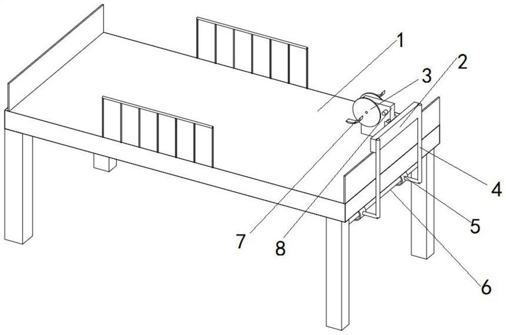
[0040] Embodiment 1: Combining all the drawings; a multi-purpose lower extremity distractor for orthopedic care, characterized in that it includes a distraction device that can be used in conjunction with a bed, and the distraction device includes an installation housing 20;

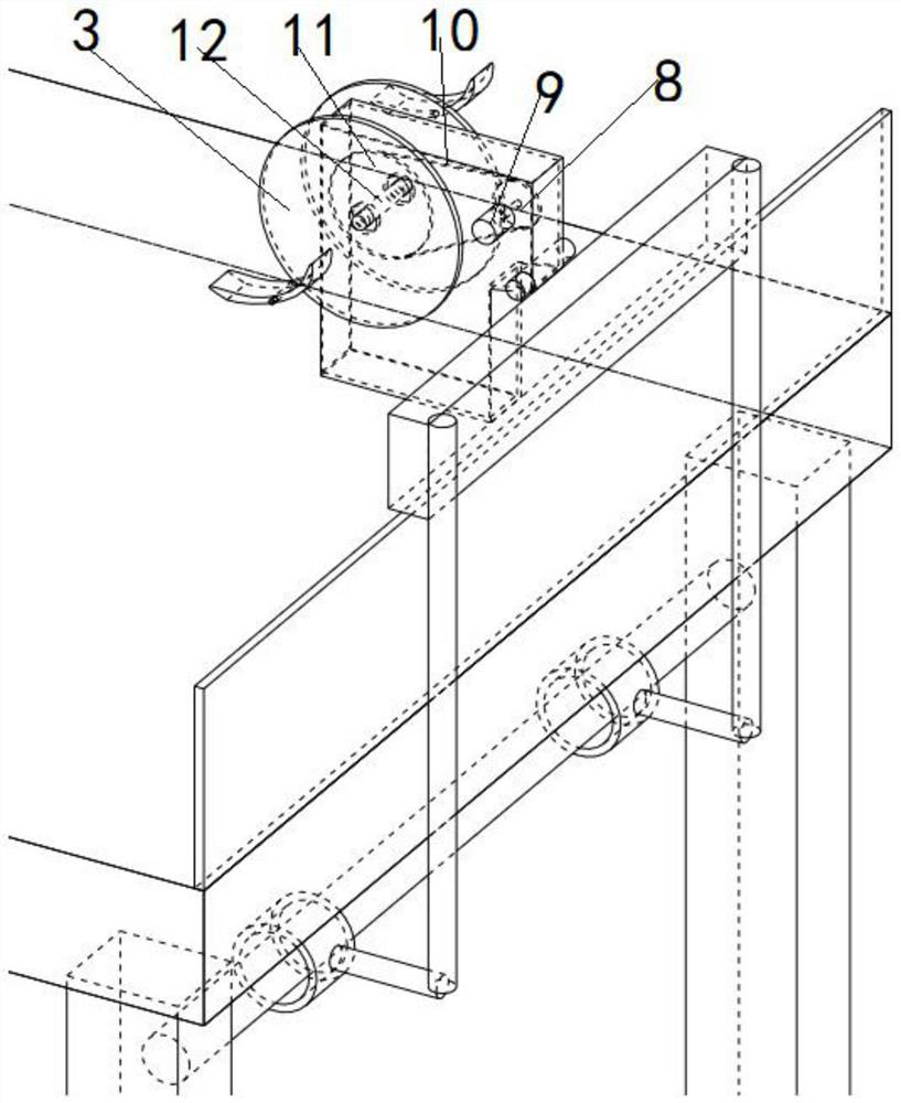
[0041] The mounting housing 20 is also installed with the driving wheel 8 and the power wheel 11, and the power shaft of the driving wheel 8 is connected to the motor 9, and the motor 9 is fixed on the mounting housing 20;

[0042] The driving pulley 8 and the power pulley 11 are powered by a belt or a chain 10;

[0043] The power wheel 11 is fixedly connected to the power shaft 12, and the two ends of the power shaft 12 are symmetrically arranged with the rotating plates 3 after passing through the installation housing 20;

[0044] The rotating plate 3 is eccentrically arranged with a foot traction column 8, and a foot traction structure 21 is rotatably mounted on the foot traction column 8;

[0045] T...

Embodiment 2

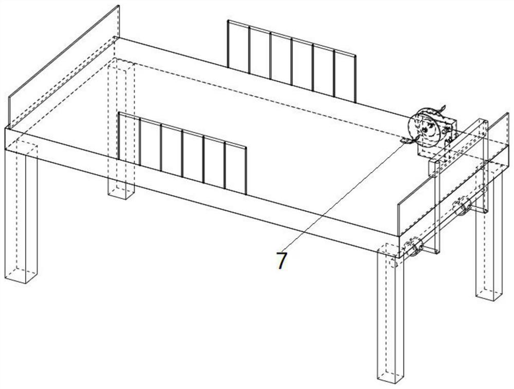
[0047]Embodiment 2: As a further improved solution or a parallel solution or an optional independent solution, the rotating plate 3 is circular, and the circular rotating plate 3 is eccentrically arranged with a plurality of adjustment holes 17, and the foot traction column 8 can be placed Different adjustment holes 17 are used to adjust the distance from the power shaft 12 . The substantial technical effect played by the technical solution here and its realization process are as follows: the present embodiment combines Figure 7 In fact, the patient's exercise range can be adjusted. For example, if the foot traction column 8 is placed in the outer adjustment hole 17, the traction range of the patient's leg will be larger.

Embodiment 3

[0048] Embodiment 3: As a further improved solution or a parallel solution or an optional independent solution, the foot traction structure 21 is a curved structure, and the foot traction structure 21 includes grooves for accommodating feet. The substantial technical effect achieved by the technical solution here and the realization process thereof are as follows: In this embodiment, the groove is used to accommodate the foot, which is a specific implementation manner.


PUM


Abstract

The invention relates to the field of medical care and army rehabilitation, in particular to a multi-purpose lower limb tractor for orthopedic nursing. The traction device can be used in cooperation with a bed and comprises a mounting shell (20); a driving wheel (8) and a power wheel (11) are mounted in the mounting shell (20), a power shaft of the driving wheel (8) is connected with a motor (9), and the motor (9) is fixed on the mounting shell (20); the power wheel (11) is fixedly connected with a power shaft (12), and rotating plates (3) are symmetrically arranged at the two ends of the power shaft (12) after the power shaft (12) penetrates through the mounting shell (20); a foot traction column (8) is eccentrically arranged on the rotating plate (3), and a foot traction structure (21) is rotatably mounted on the foot traction column (8); a foot can be placed on the foot traction structure (21) to be subjected to traction movement; the foot traction structures (21) on the two rotating plates (3) are symmetrically arranged around the center of the power shaft (12).

Description

technical field [0001] The present invention relates to the field of medical care and army rehabilitation, in particular to a multipurpose lower limb distractor for orthopaedic care. Background technique [0002] At present, there are more and more bedridden patients. The bedridden patients include young people, old people, and children. Different people have different leg widths; and different people have different physical conditions. Some have a certain ability to exercise, and some even There is no basic exercise ability. [0003] Taking "cam and width and bed" as the abstract keyword, searched in the Chinese patent publication database; [0004] After reading through these articles, it is found that these existing technologies all have the following outstanding defects: [0005] The structure is complex, and after being manufactured, it basically cannot be used as an ordinary bed; and the width of the legs of different patients is not fully considered, and the range o...

Claims


Application Information

Patent Timeline
Patent Type & Authority Applications(China)
IPC IPC(8): A61H1/02
CPCA61H1/0237A61H2201/0142A61H2201/1207A61H2205/10A61H2205/12
Inventor 王玲娟刘艳武赵诣林
Owner FOURTH MILITARY MEDICAL UNIVERSITY
Why Eureka
Try Eureka