Gas-liquid force increasing mechanism

A gas-liquid boosting and gas-liquid technology, applied in mechanical equipment, fluid pressure converters, etc., can solve the problems of stamping products such as quality problems, unstable pressure, large resistance changes, etc., to achieve stable and reliable products, quality assurance, even force effect

Active Publication Date: 2011-05-25
苏州托克斯冲压设备有限公司
View PDF0 Cites 0 Cited by
  • Summary
  • Abstract
  • Description
  • Claims
  • Application Information

AI Technical Summary

Problems solved by technology

[0003] However, under the prior art, this kind of gas-hydraulic booster cylinder still has a common defect: during the process and return movement, the compression and release of the gas will produce a very fast impact in the cylinder. The difference in compressibility is so great that the high-pressure oil driven by compressed air has no time to replenish, so the oil pressure drops rapidly, and the oil pressure will not be enough to continue to drive the working piston forward, that is, it stops moving forward. At this time, it is necessary to wait for the compressed air to boost again to continue. Push the oil pressure up to generate a new force stroke again
Such pauses, pressure boosting, and forward reciprocation occur, causing the gas-hydraulic force boosting mechanism to crawl one fast and one slow during press-fitting work with a long force stroke, and cannot operate effectively and continuously. Yes, the resistance changes greatly, so the pressure is extremely unstable, which eventually leads to quality problems in stamping products

Method used


Image

  • Gas-liquid force increasing mechanism
  • Gas-liquid force increasing mechanism
  • Gas-liquid force increasing mechanism

Examples


Embodiment 1

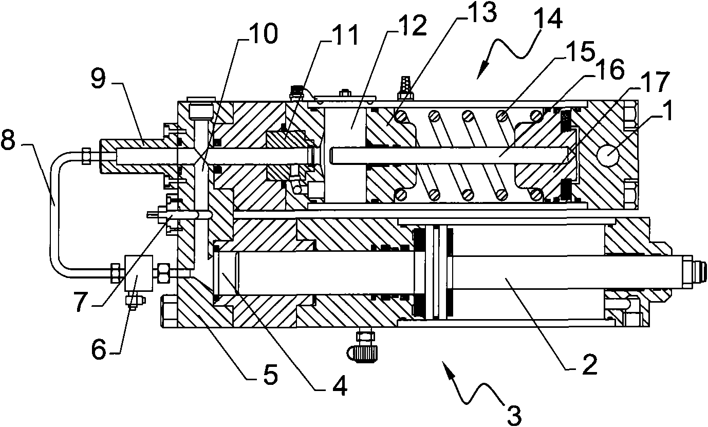
[0027] See attached figure 1 And attached Figure 4 , a gas-liquid booster mechanism, which includes a working pressure cylinder 3 and a gas-liquid booster 14 fixedly arranged on the working pressure cylinder 3 for applying thrust to the working pressure cylinder 3, the gas-liquid booster 14 and the working The pressure cylinder 3 is integrally fixed. The working pressure cylinder 3 has a first oil storage chamber 4, an output chamber, and a working piston rod 2 located between the first oil storage chamber 4 and the output chamber. The pressure in the output chamber is constant, and the working piston rod 2 outputs punching force; gas-liquid The booster 14 has a second oil storage chamber 12, an air storage chamber, and a booster piston rod 16 between the second oil storage chamber 12 and the air storage chamber. The air storage chamber has an air inlet 1, and the air inlet The hole 1 is connected with the high-pressure air source, and one end of the booster piston rod 16 i...

Embodiment 2

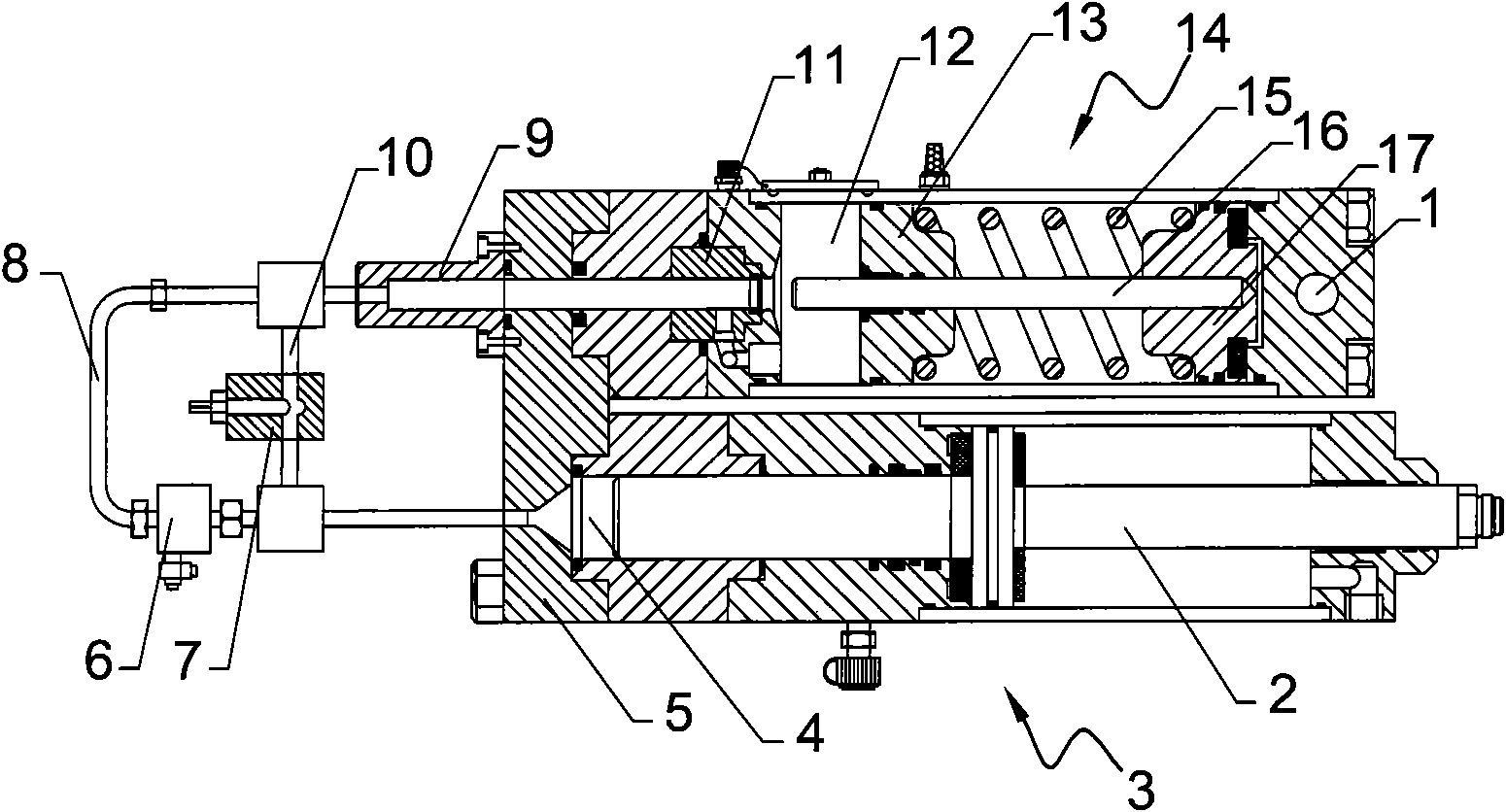
[0033] See attached figure 2 And attached Figure 8 , the difference between this embodiment and the first embodiment is that the first channel 10 and the second channel 8 are both pipe bodies arranged on the flange cover 5, at this time, the first channel 10 and the second channel 8 can be arranged on the flange cover 5, the advantage of this method is that the first channel 10 and the second channel 8 are located outside the cylinder, the throttle valve 7 and the electromagnetic reversing valve 6 are also located outside the cylinder, and any problem with any part can be solved. It is convenient to replace; those skilled in the art can also find out that this embodiment can also be an attached Figure 9 The constructions shown serve as equivalent transformations.

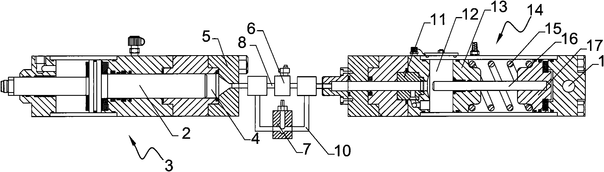
[0034] See attached image 3 As shown, since the first channel 10 and the second channel 8 are both externally placed, the gas-liquid booster mechanism can be set as a split type, so that it can be connected by ...

Embodiment 3

[0036] See attached Figure 10 And attached Figure 11 , is the main cross-sectional view of the flange cover 5 of the third embodiment. In this embodiment, the first channel 10 and the second channel 8 are set inside the flange cover 5. The mechanism design is tight, which can greatly reduce the gas-liquid boost body size.

[0037] From the above embodiments, it is not difficult to see that the present invention is a simple and practical structure, coherent operation, stable and reliable gas-hydraulic booster mechanism.


PUM


Abstract

The invention discloses a gas-liquid force increasing mechanism which comprises a working pressure cylinder and a gas-liquid force increasing device used for applying thrust on the working pressure cylinder, wherein the working pressure cylinder is provided with a first oil storage cavity, an output cavity and a working piston rod positioned between the first oil storage cavity and the output cavity; the gas-liquid force increasing device is provided with a second oil storage cavity, a gas storage cavity and a force increasing piston rod arranged between the second oil storage cavity and the gas storage cavity; a first channel is arranged between the first and the second oil storage cavities and is internally provided with a throttling valve used for controlling the flow speed of hydraulic oil; a second channel is also arranged between the first and the second oil storage cavities and is internally provided with an electromagnetic directional valve used for controlling the second channel to open or close. The gas-liquid force increasing mechanism solves the problems in the prior art, and has the advantages of being simple and practical in structure, continuous in running, stable and reliable.

Description

technical field [0001] The invention relates to a gas-liquid booster mechanism, in particular to a gas-liquid booster mechanism for stamping equipment. Background technique [0002] At present, there is a gas-hydraulic booster cylinder in the stamping equipment. The gas-hydraulic booster cylinder is mainly composed of a working cylinder and a gas-hydraulic booster, which can provide a large and continuous impact force for the stamping equipment. Equipped with a gas-hydraulic booster cylinder, the appearance structure of the stamping equipment is reduced, which is convenient for installation at any angle; the internal structure adopts the design of isolating hydraulic oil and compressed air, and is equipped with a special air circuit and control valve to ensure the contact between the piston rod of the working cylinder. The force stroke is automatically started after the workpiece is finished, and it has the functions of small fast forward force and return force, fast stroke ...

Claims


Application Information

Patent Timeline
Patent Type & Authority Patents(China)
IPC IPC(8): F15B3/00B21D22/00
Inventor 夏元海龚革新
Owner 苏州托克斯冲压设备有限公司
Why Eureka
Try Eureka