Eureka AIR delivers breakthrough ideas for toughest innovation challenges, trusted by R&D personnel around the world.

Electric heating type U-shaped hot material heat preservation conveying groove and spiral heat preservation conveyor for transferring hot materials

A conveying trough, electric heating technology, applied in the field of U-shaped heat preservation conveying trough, can solve the problems of limited number of characters, lack of heating and heat preservation function of U-shaped trough, and cannot meet the needs of special screw conveyor heat preservation and heat transfer materials, etc., to achieve Good effect, guaranteed drying effect, and compact structure

Pending Publication Date: 2022-07-08
JINGJIN ENVIRONMENTAL PROTECTION INC
View PDF16 Cites 1 Cited by
  • Summary
  • Abstract
  • Description
  • Claims
  • Application Information

AI Technical Summary

Problems solved by technology

[0006] The purpose of the present invention is to overcome the defects of the existing single-layer U-shaped normal-temperature feeding trough, solve the technical problem that the U-shaped feeding trough lacks the function of heating and heat preservation, and cannot meet the needs of special screw conveyor users for heat preservation and heat transfer materials, and provides a An electric heating type U-shaped heating material heat preservation conveying tank and a spiral heat preservation conveyor for transferring heat materials; a spiral heat preservation conveyor for transferring heat materials—refers to a spiral heat preservation device for transferring heat materials having an electric heating type U-shaped heat preservation conveying groove for heat materials of the present invention Conveyor, abbreviated due to the limited number of characters in the patent name

Method used


Image

  • Electric heating type U-shaped hot material heat preservation conveying groove and spiral heat preservation conveyor for transferring hot materials
  • Electric heating type U-shaped hot material heat preservation conveying groove and spiral heat preservation conveyor for transferring hot materials
  • Electric heating type U-shaped hot material heat preservation conveying groove and spiral heat preservation conveyor for transferring hot materials

Examples


Embodiment 1

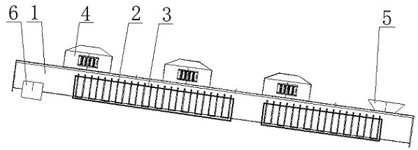
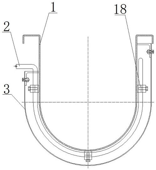
[0028]An electric heating U-shaped heat preservation conveying trough 21 (abbreviation: U-shaped heat preservation conveying trough), the main point of the innovative overall implementation scheme is to improve the existing single-layer U-shaped normal temperature conveying trough into a coated insulation layer The electric heating U-shaped heat insulation conveying tank 21 includes U-shaped feeding chute 1, electric heating insulation layer 3, tank cover parts, and sealing groove end plate 22; mainly to add electric heating insulation layer, including electric heating pipe 2, U-shaped insulation layer Layer 3; the electric heating insulation layer covers the U-shaped feeding chute 1, the sealing groove end plates 22 are welded on both ends of the U-shaped feeding chute 1, and the trough cover parts cover the U-shaped feeding chute 1 to form a U-shaped heat preservation conveying Slot 21; while the screw conveyor conveys the hot material in the U-shaped feeding trough 21, the e...

Embodiment 2

[0036] A spiral heat preservation conveyor for transferring hot material (abbreviation: spiral heat preservation conveyor), which is to transfer the hot material (hot filter cake) of a filter press to a spiral heat preservation conveyor of a filter cake dryer, using the electric heating U type provided by the present invention. 21-shaped thermal insulation conveying trough 21 (abbreviation: U-shaped thermal insulation conveyor); the spiral thermal insulation conveyor is mainly composed of a screw drive device, a shaft screw device, and a U-shaped thermal insulation conveyor trough 21; It is suitable for high output non-viscous non-winding hot materials within 70 meters. The technical part shared by the present invention and the prior art is manufactured in accordance with the current standard "Screw Conveyor" JB / T 7679 of my country's machinery industry.

[0037] The screw drive device includes a motor drive device, a machine head coupling, and a common base 23; the set motor ...


PUM


Abstract

The invention discloses an electric heating type U-shaped hot material heat preservation conveying groove and a spiral heat preservation conveyor for transferring hot materials. The U-shaped heat preservation conveying groove comprises a U-shaped conveying groove body, an electric heating heat preservation layer, a groove cover component and a groove sealing end plate. According to the innovative scheme, a U-shaped electric heating heat preservation layer is additionally arranged on the periphery of an existing U-shaped conveying groove and comprises an electric heating pipe, a U-shaped heat preservation cover and heat insulation cotton. An existing U-shaped material conveying groove is adaptively improved, the U-shaped material conveying groove is wrapped by the electric heating heat preservation layer, the groove sealing end plates are welded to the two ends of the U-shaped material conveying groove, the material conveying groove is covered with the groove cover, and the electric heating temperature is adjustable; and on-line electric heating continuous heat preservation can be carried out on hot materials in the transfer conveying process in the U-shaped material conveying groove, so that the hot materials do not deform in the transfer process. According to the spiral heat preservation conveyor, the U-shaped heat preservation conveying groove is used, and the technical problems that a U-shaped conveying groove lacks the heating and heat preservation function and cannot meet the requirement of a special spiral conveyor user for heat preservation and transfer of heat transfer materials are solved. The post-drying treatment effect of hot materials is guaranteed; the product is upgraded and updated, and energy and efficiency are increased.

Description

technical field [0001] The invention belongs to the technical field of a shafted screw conveyor for transferring heated materials from a filter press to a dryer, and relates to a U-shaped heat preservation conveying trough for transferring heated materials. Background technique [0002] The screw conveyor is a kind of equipment that uses the motor to drive the screw to rotate and push the material to achieve the purpose of closed conveying; the screw conveyor with a shaft is a screw conveyor with a screw center shaft and a screw blade that does not touch the bottom of the trough; The heat preservation conveyor refers to the shafted screw conveyor for the heat preservation and transfer of hot materials (such as hot filter cakes that need post drying treatment) for heat preservation and transfer, that is, the intermediate process equipment of the filter press and the dryer; mainly by the screw drive device, It is composed of a shaft screw device and a U-shaped feeding chute; i...

Claims


Application Information

Patent Timeline
Patent Type & Authority Applications(China)
IPC IPC(8): B65G33/24B65G33/14F26B23/06
CPCB65G33/24B65G33/14F26B23/06
Inventor 贾海瑞王庆森姚洪恒路庆杰周博金龙
Owner JINGJIN ENVIRONMENTAL PROTECTION INC
Why Eureka
Eureka Blog
Learn More