
Image sensor package utilizing a removable protection film and method of making the same

An image sensor and protective film technology, which is applied in the field of image sensor packaging structure using removable protective film, can solve the problems of pollution, particle removal, etc., achieve high yield, and promote the effect of simplification of procedures

Inactive Publication Date: 2009-01-07
ADVANCED CHIP ENG TECH INC
View PDF1 Cites 28 Cited by
  • Summary
  • Abstract
  • Description
  • Claims
  • Application Information

AI Technical Summary

Problems solved by technology

[0006] Conventional methods of packaging image sensor components using chip-on-chip (COB) or leaded chip-on-chip (LCC) with wire-bonding structures suffer from yield issues during the process due to the inability to post-process on the microlens area. Removed Particle Pollution

Method used


Image

  • Image sensor package utilizing a removable protection film and method of making the same
  • Image sensor package utilizing a removable protection film and method of making the same
  • Image sensor package utilizing a removable protection film and method of making the same

Examples


Embodiment Construction

[0041] The present invention will be described in detail with preferred embodiments and accompanying drawings. However, those skilled in the art will appreciate that the preferred embodiments of the present invention are described by way of illustration rather than limiting the claims of the present invention. The present invention is widely practiced in other embodiments than the preferred embodiment explicitly described herein, and the scope of the present invention is not particularly limited except as expressly defined in the appended claims.

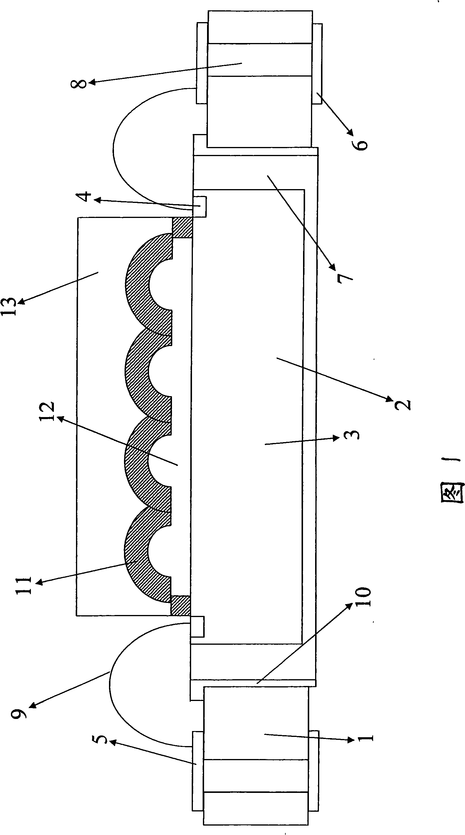
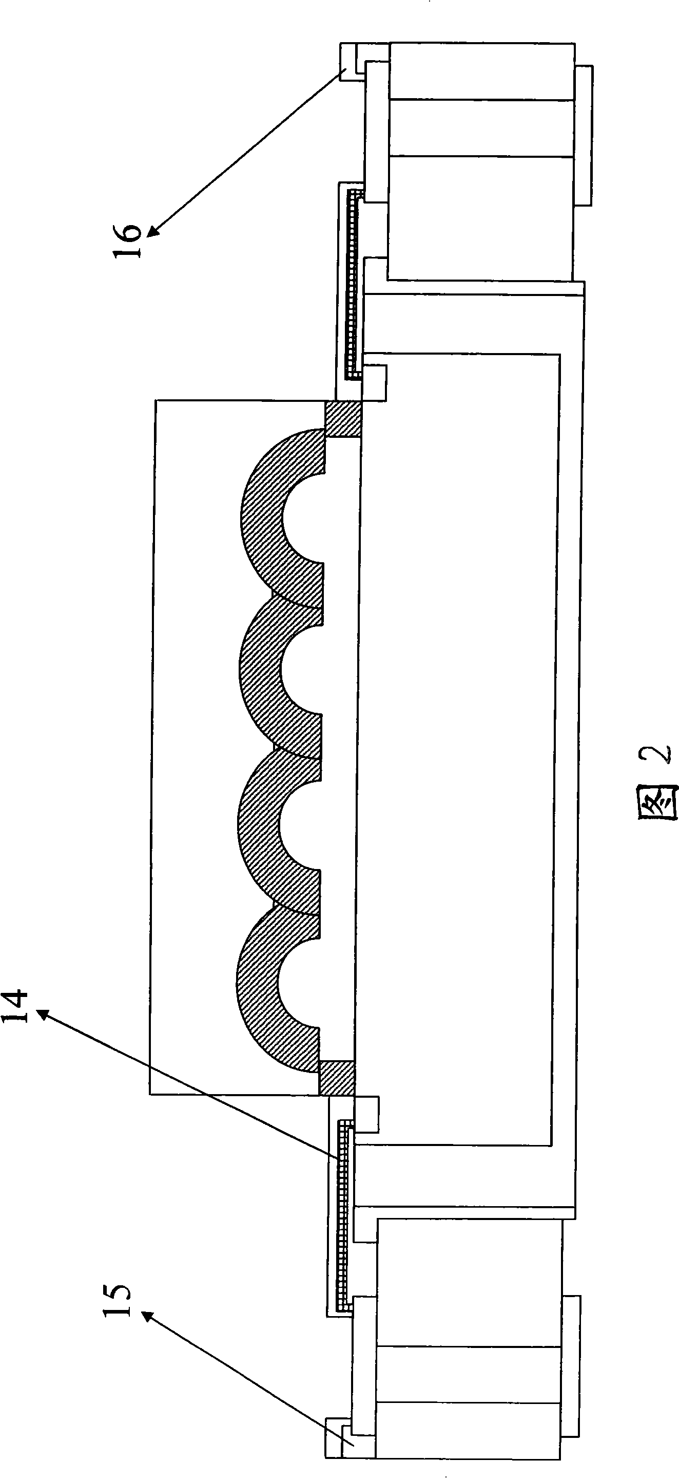
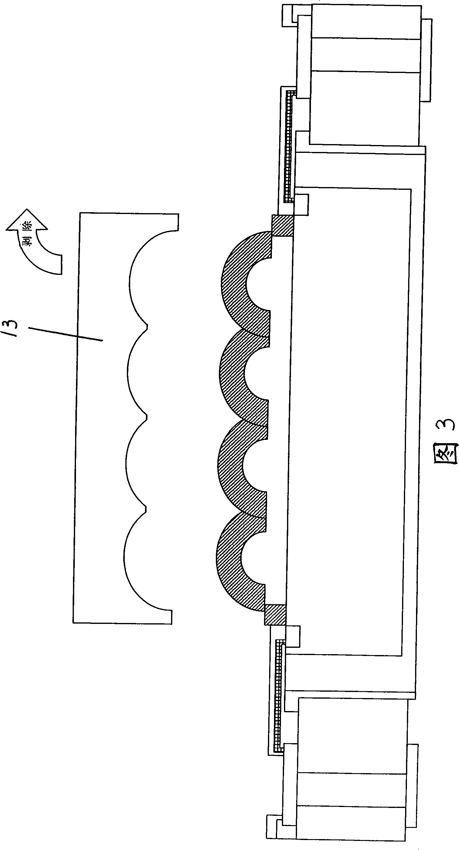
[0042] The invention discloses an image sensor packaging structure using a removable protective film. FIG. 1 is a schematic cross-sectional view illustrating a silicon wafer package of an image sensor according to an embodiment of the present invention. As shown in FIG. 1 , the silicon wafer package structure includes a substrate 1 having a die receiving hole 2 formed therein for receiving a die 3 . The width dimension of die rece...


PUM


Abstract

The invention discloses an image sensor package structure employing removable protective film. The structure comprises substrate possessing crystal grain receiving hole and intercommunicating through-hole. Terminal pad forms beneath intercommunicating through-hole, metal pad forms on upper surface of substrate. The crystal grain is configured in crystal grain receiving hole by adhesive material. Output and input welding pad forms on upper edge of crystal grain. Coupling wire couples to metal pad and output and input welding pad. The protective layer forms on upper of micro-lens area to prevent pollution of micro-lens from crystal grain. The removable protective film forms on upper of protection layer to prevent micro-lens from water, oil, dust and temporary impact during packaging and assembling procedures.

Description

Technical field: [0001] The present invention relates to image sensor packaging structures, and more particularly to image sensor packaging structures utilizing removable protective films. Background technique: [0002] In the field of semiconductor devices, the density of devices continues to increase and the size of devices continues to shrink. In order to cope with the above situation, the demand for packaging or interconnection technology in such high-density components is also increasing. Traditionally, an array of solder bumps is formed on the surface of a die in a flip-chip attachment method. Solder bump formation can be performed through a solder mask using a solder composite material for producing the desired solder bump morphology. The functions of chip packaging include power distribution, signal distribution, heat dissipation, protection and support, etc. As semiconductors become more complex, traditional packaging technologies such as lead frame packaging, fl...

Claims


Application Information

Patent Timeline
Patent Type & Authority Applications(China)
IPC IPC(8): H01L27/146H01L23/28H01L23/29H01L21/56
CPCH01L27/14627H01L27/14687H01L2924/10253H01L27/14618H01L2224/48091H01L2924/00014H01L2924/00H01L23/02H01L27/146
Inventor 杨文焜张瑞贤李基城杨文彬
Owner ADVANCED CHIP ENG TECH INC
Learn More