High-rotating-speed and high-power hydraulic coupler speed regulating device capable of achieving intelligent cooling

A technology of hydraulic coupler and speed control device, which is applied in clutches, clutches, rotary couplings, etc., which can solve the problems of inconvenient installation, poor cooling effect of hydraulic coupler speed control device, and influence on hydraulic coupler speed control device Cooling effect and other issues, to achieve the effect of easy cooling

Pending Publication Date: 2022-07-08
陈振胜
View PDF0 Cites 0 Cited by
  • Summary
  • Abstract
  • Description
  • Claims
  • Application Information

AI Technical Summary

Problems solved by technology

[0004] 1. The existing high-speed and high-power hydraulic coupler speed control device that can be cooled intelligently has a poor cooling effect on the hydraulic coupler speed control device, so the normal operation of the hydraulic coupler speed control device has a great impact Impact;
[0005] 2. The existing high

Method used


Image

  • High-rotating-speed and high-power hydraulic coupler speed regulating device capable of achieving intelligent cooling
  • High-rotating-speed and high-power hydraulic coupler speed regulating device capable of achieving intelligent cooling
  • High-rotating-speed and high-power hydraulic coupler speed regulating device capable of achieving intelligent cooling

Examples


Example Embodiment

[0038] Example 1

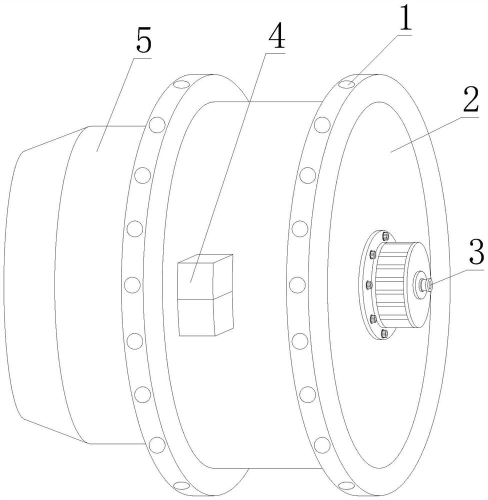
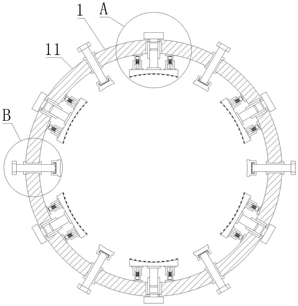
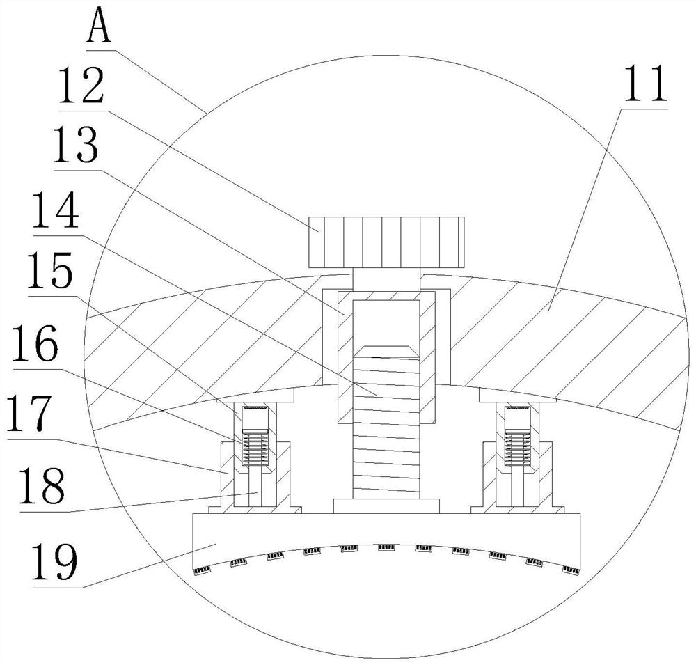
[0039] like Figure 1-7 As shown, the present invention provides a high-speed and high-power hydraulic coupler speed regulating device capable of intelligent cooling, comprising a cooling structure 2, an air supply pump 3 is fixedly installed at the right end of the cooling structure 2, and both ends of the cooling structure 2 are fixedly installed There is an annular fixed structure 1, a cooling device 4 is fixedly installed on the front of the outer wall of the cooling structure 2, and a hydraulic coupling speed regulating device body 5 is fixedly installed on the inner wall of the annular fixed structure 1. The annular fixed structure 1 includes a metal fixing ring 11, which is fixed by metal. One side of the ring 11 is fixedly installed with one end of the cooling structure 2, the outer wall of the metal fixing ring 11 is rotatably connected with an adjusting nut 12, the inner wall of the metal fixing ring 11 is fixedly installed with a guide column 15, ...

Example Embodiment

[0041] Example 2

[0042] like Figure 1-7 As shown, on the basis of Embodiment 1, the present invention provides a technical solution: preferably, a threaded adjusting sleeve 13 is fixedly installed at the bottom of the adjusting nut 12 and located on the front of the metal fixing ring 11, and the inner wall of the threaded adjusting sleeve 13 is threadedly connected There is a threaded push rod 14, the bottom of the threaded push rod 14 is fixedly installed with a pressure plate 19, the bottom of the outer wall of the guide column 15 is inserted with a guide sleeve seat 17, the bottom of the inner wall of the guide sleeve seat 17 is fixedly installed with a pull rod 18, and the top of the outer wall of the pull rod 18 is fixedly installed And a spring 16 is arranged on the front of the guide column 15, the bottom of the guide sleeve seat 17 is fixedly installed with the two ends of the top of the pressure plate 19, the inner wall of the threaded sleeve 110 is threadedly conn...

Example Embodiment

[0044] Example 3

[0045] like Figure 1-7 As shown, on the basis of Embodiment 1, the present invention provides a technical solution: preferably, the fixing block 22 includes a fixing plate 229, the bottom of the fixing plate 229 is fixedly installed with the inner wall of the metal ring sleeve 21, and the top of the fixing plate 229 is fixedly installed. A fixed screw sleeve 227 is fixedly installed, the inner wall of the fixed screw sleeve 227 is threadedly connected with a locking stud 226, the outer wall of the locking stud 226 is inserted with a pipe clip 225, and the top of the locking stud 226 is inserted with a fixed pressure plate 223 , the top of the fixed pressure plate 223 is fixedly installed with a fixed screw 222, the top of the fixed screw 222 and the top of the protective net 25 are threadedly connected with a compression nut 221, and the outer wall of the locking stud 226 is located between the fixed pressure plate 223 and the pipe clip 225. A first spring...


PUM


Abstract

The invention discloses an intelligent-cooling high-rotating-speed high-power hydraulic coupler speed regulating device, and relates to the technical field of hydraulic couplers, the intelligent-cooling high-rotating-speed high-power hydraulic coupler speed regulating device comprises a cooling structure, an air supply pump is fixedly mounted at the right end of the cooling structure, and annular fixing structures are fixedly mounted at the two ends of the cooling structure; a refrigerating device is fixedly installed on the front face of the outer wall of the cooling structure, and a hydraulic coupler speed adjusting device body is fixedly installed on the inner wall of the annular fixing structure. According to the hydraulic coupler speed regulating device, the threaded adjusting sleeve rotates by rotating the adjusting nut, the threaded push rod is pushed out of the inner wall of the threaded adjusting sleeve, the inner wall of the pressing plate is in lap joint with the outer wall of the hydraulic coupler speed regulating device body, and therefore the annular fixing structure is fixed to the outer wall of the hydraulic coupler speed regulating device body; and a certain gap is formed between the outer wall of the hydraulic coupler speed regulation device body and the inner wall of the cooling structure, so that the hydraulic coupler speed regulation device body can be cooled conveniently.

Description

technical field [0001] The invention relates to the technical field of hydraulic couplers, in particular to a high-speed and high-power hydraulic coupler speed regulating device capable of intelligent cooling. Background technique [0002] With the continuous development of modern industry, my country's demand for petroleum energy is increasing, so the degree of oil exploitation is also increasing year by year. As an important part of the oil drilling system, the hydraulic coupling speed control device is a system One of the important equipments that transmit power in drilling rigs, its convenience, reliability and functionality are the keys to ensuring drilling quality and efficiency. [0003] The following problems exist for the prior art: [0004] 1. The existing high-speed and high-power hydraulic coupling speed control device that can be intelligently cooled has the problem of poor cooling effect on the hydraulic coupling speed control device, so the normal operation of...

Claims


Application Information

Patent Timeline
IPC IPC(8): F16D33/18F16H57/04F16H57/028
CPCF16D33/18F16H57/0416F16H57/028Y02E10/20
Inventor 陈振胜
Owner 陈振胜
Why Eureka
Try Eureka