Oil-immersed transformer release valve capable of preventing oil oxidation
A technology for oil-immersed transformers and release valves, which is applied in transformer/inductor cooling, valve operation/release devices, valve details, etc. It can solve problems such as poor sealing effect, inability to cut off the oil tank, and up and down movement of the membrane disc, etc., to achieve Good sealing effect, increase the effect of sealing strength
- Summary
- Abstract
- Description
- Claims
- Application Information
AI Technical Summary
Problems solved by technology
Method used
Image
Examples
Embodiment 1
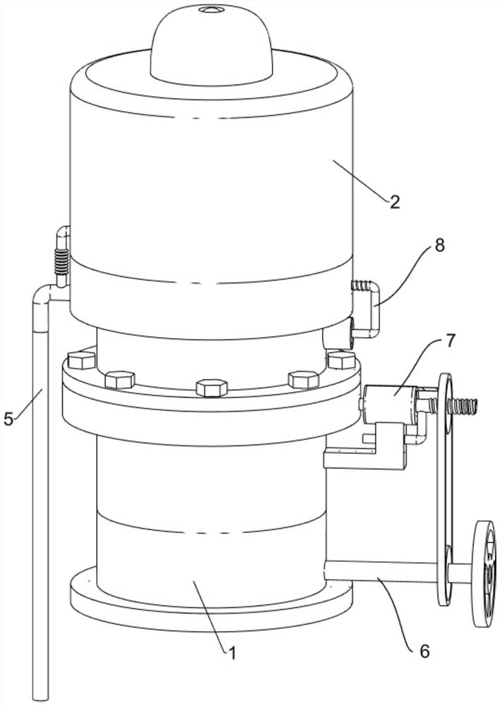
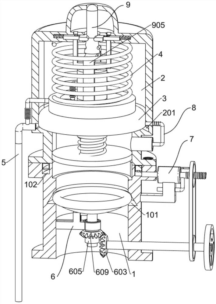
[0028] An oil-immersed transformer release valve that prevents oil oxidation, such as figure 1 , figure 2 , Image 6 and Figure 7 As shown, it includes a valve seat 1, a valve body 2, a sealing ring 204, a diaphragm 3, a first spring 4, an oil outlet pipe 5, a partition mechanism 6, a sealing mechanism 7, a low pressure sensing mechanism 8 and a marking mechanism 9. The valve seat 1 is welded, the upper part of the valve seat 1 is provided with a circular truncated groove 101, the upper part of the valve seat 1 is provided with a cylindrical cavity 102, the cylindrical cavity 102 is located above the circular truncated groove 101, and the upper part of the valve seat 1 is connected with a valve body 2 by bolts. Two left-right symmetrical first rectangular grooves 202 are opened above the body 2, two left-right symmetrical vertical second rectangular grooves 203 are formed above the valve body 2, and the two second rectangular grooves 203 are respectively connected to the a...
Embodiment 2
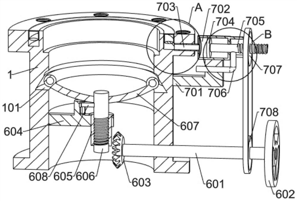
[0031] On the basis of Example 1, as figure 2 and image 3 As shown, the partition mechanism 6 includes a shaft 601, a turntable 602, a first bevel gear 603, a T-shaped fixing rod 604, a sleeve 605, a screw 606, a special-shaped housing 607, a T-shaped limit block 608 and a second bevel gear 609 , the lower right side of the valve seat 1 is rotatably provided with a rotating shaft 601, the right end of the rotating shaft 601 is fixedly connected with a turntable 602, the left end of the rotating shaft 601 is fixedly connected with a first bevel gear 603, and the left part of the inner side of the valve seat 1 is fixedly connected with a T-shaped fixing rod 604, The right part of the T-shaped fixing rod 604 is rotated with a sleeve 605, the inner surface of the sleeve 605 is provided with threads, a screw 606 is arranged in the sleeve 605, the screw 606 is threaded with the sleeve 605, and the upper part of the screw 606 is fixed with a special-shaped shell 607, the special-s...
PUM
 Abstract
Description
Claims
Application Information
 - R&D
- Intellectual Property
- Life Sciences
- Materials
- Tech Scout
- Unparalleled Data Quality
- Higher Quality Content
- 60% Fewer Hallucinations
Browse by: Latest US Patents, China's latest patents, Technical Efficacy Thesaurus, Application Domain, Technology Topic, Popular Technical Reports.
© 2025 PatSnap. All rights reserved.Legal|Privacy policy|Modern Slavery Act Transparency Statement|Sitemap|About US| Contact US: help@patsnap.com


