
Cylinder cylindrical surface groove line precision detection device and method based on projection trajectory recovery

A technology of projection trajectory and accuracy detection, applied in measurement devices, mechanical measurement devices, and mechanical devices, etc., can solve the problems of unstable test accuracy, low efficiency, complicated operation, etc., and achieve simple and easy measurement data processing and adjustment speed. Fast and efficient measurement results

Active Publication Date: 2022-07-08
XI'AN INST OF OPTICS & FINE MECHANICS - CHINESE ACAD OF SCI +1
View PDF10 Cites 0 Cited by
  • Summary
  • Abstract
  • Description
  • Claims
  • Application Information

AI Technical Summary

Problems solved by technology

[0005] The purpose of the present invention is to solve the shortcomings of the existing cylindrical groove line accuracy detection method, such as complex operation, low intelligence, low efficiency, and unstable test accuracy, which can not meet the requirements of high precision and batch detection, and provide a A device and method for detecting the accuracy of cylinder cylinder groove line based on projection trajectory restoration

Method used


Image

  • Cylinder cylindrical surface groove line precision detection device and method based on projection trajectory recovery
  • Cylinder cylindrical surface groove line precision detection device and method based on projection trajectory recovery
  • Cylinder cylindrical surface groove line precision detection device and method based on projection trajectory recovery

Examples


Embodiment Construction

[0028] The present invention will be further described below with reference to the accompanying drawings and exemplary embodiments.

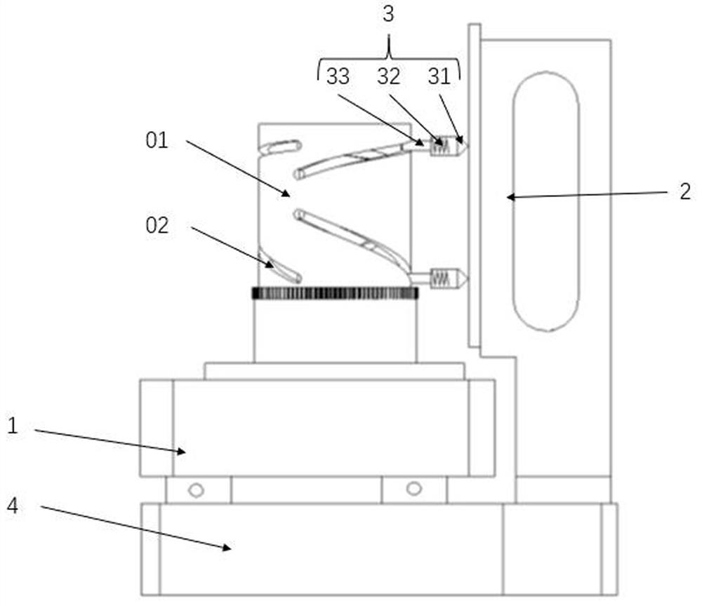
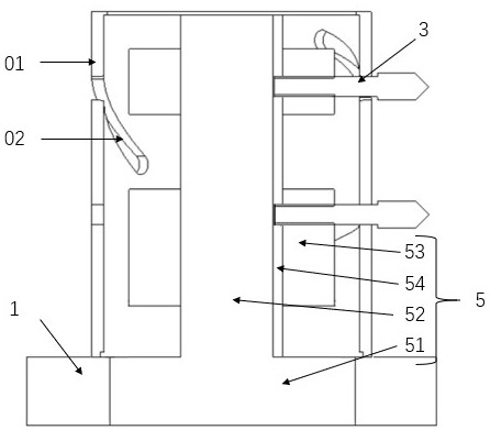
[0029] refer to figure 1 and figure 2 , a cylinder-cylindrical groove line accuracy detection device based on projection trajectory restoration, comprising an annular turntable 1 , a marking plate 2 , two marking pens 3 , a translation stage 4 and an adjustment assembly 5 .

[0030] The cylinder 01 to be inspected is a hollow structure with at least one cylindrical groove line 02 on it. The cylindrical body 01 to be inspected includes at least one equal diameter section, and each cylindrical groove line 02 is located in the same equal diameter section; in this embodiment, The cylinder 01 to be inspected is an equal diameter cylinder, and two cylindrical groove lines 02 are arranged on the cylinder 01 to be inspected.

[0031] The marking plate 2 is arranged on a fixed base on one side of the translation stage 4; the annular turntable 1 and th...


PUM


Abstract

The invention relates to optical precision instrument detection equipment and method, in particular to a cylinder and cylindrical surface trough line precision detection device and method based on projection track recovery, and aims to solve the problems that an existing cylindrical surface trough line precision detection method is complex in operation, low in intelligent degree, low in efficiency, unstable in test precision and poor in detection precision. And therefore, the high-precision and batch detection requirements cannot be met. The cylinder cylindrical surface groove line precision detection device based on projection track restoration comprises an annular rotary table, a marking plate, a marking pen, a translation table and an adjusting assembly. According to the invention, the marking pen is used as a leading point of the cylindrical trough line to perform track recovery on the cylindrical trough line on the marking plate, so that the effects of automatic intelligent operation and whole-course stable test can be realized, and the high-precision detection requirements of various optical loads on the cylindrical trough line can be met. Meanwhile, the invention discloses a cylinder and cylindrical surface groove line precision detection method based on projection track recovery.

Description

technical field [0001] The invention relates to detection equipment and methods for optical precision instruments, in particular to a detection device and detection method for the accuracy of cylindrical groove lines based on projection trajectory restoration. Background technique [0002] With the increasing demand for imaging on the ground and in the aviation and aerospace fields, the research and development of precision optical payloads for imaging is becoming more and more urgent. In order to meet the requirements of the field of view change of the precision optical load, the interval between some optical components must be adjusted accurately. The cylindrical groove line drives the guide post to drive the movement of the optical components to meet the high integration and high precision of the precision optical load system. A common innovative application method required. [0003] The machining of the cylindrical groove line needs to be designed according to the techn...

Claims


Application Information

Patent Timeline
IPC IPC(8): G01B5/00G01M11/02
CPCG01B5/00G01M11/0242
Inventor 杨洪涛陈卫宁张广栋程塨王长青彭建伟
Owner XI'AN INST OF OPTICS & FINE MECHANICS - CHINESE ACAD OF SCI
Learn More