
Eye shaping designer with accurate measurement

A technology of eye plastic surgery and designer, applied in the direction of eye testing equipment, diagnostic recording/measurement, sensors, etc., can solve the problems of distance deviation, effect effect, inconvenient design tools, etc., to achieve precise control, avoid distance deviation, prevent The effect of distance bias

Pending Publication Date: 2022-07-12
商丘市第一人民医院
View PDF0 Cites 0 Cited by
  • Summary
  • Abstract
  • Description
  • Claims
  • Application Information

AI Technical Summary

Problems solved by technology

[0003] Before eye plastic surgery, it is necessary to measure and draw the design of the eye, but the existing technology is not convenient to accurately control the design tool in actual use, and it is easy to cause distance deviation with the use of misuse, which makes the drawing The accuracy of the line is low, which will affect the postoperative effect

Method used


Image

  • Eye shaping designer with accurate measurement
  • Eye shaping designer with accurate measurement
  • Eye shaping designer with accurate measurement

Examples


Embodiment 1

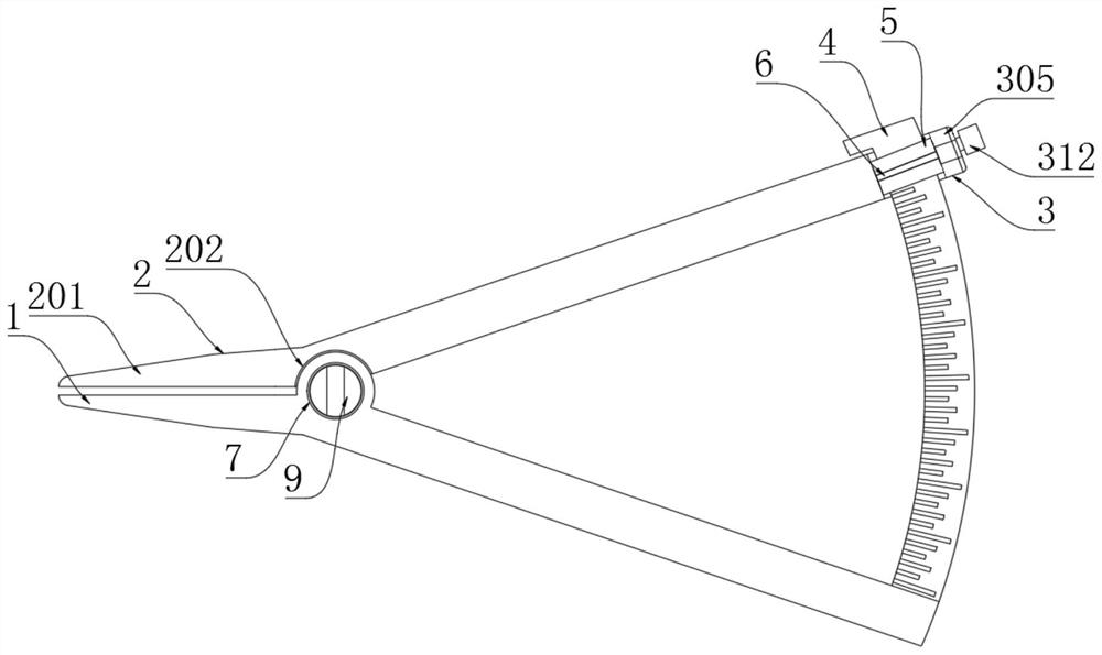
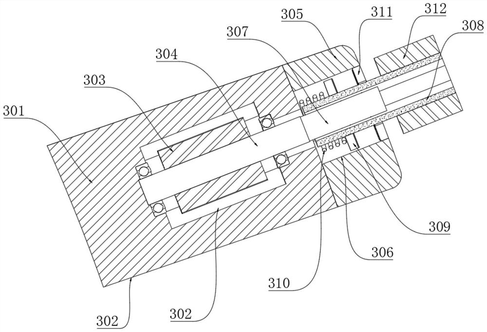
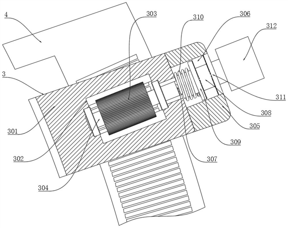
[0041] see Figure 1-4 and 6, the present invention provides a technical solution: including a rotating arm 1, a design measuring assembly 2 and a stable driving assembly 3, the design measuring assembly 2 is rotatably arranged in the middle of the rotating arm 1 and is used to cooperate with the rotating arm 1 and be on the dial The measured length is shown on 4, and the rotating arm 1 and the design measuring assembly 2 are rotated relative to each other, and the part of the tip of the rotating arm 1 and the design measuring assembly 2 is used as a reference for measurement, wherein the design measuring assembly 2 includes a rotating setting with the rotating arm 1. The first measuring arm 201, the first fixing block 301 is welded on one end of the first measuring arm 201 corresponding to the position of the dial 4, and one end of the first measuring arm 201 corresponding to the position of the positioning column 9 is provided with a first groove 202, The inner wall of a gro...

Embodiment 2

[0047] see Figure 5-7 The difference from the first embodiment is that a concave ring is opened in the middle of the positioning column 9, and the inner wall of the concave ring is movably connected with a torsion spring 204. The first measuring arm 201 and the rotating arm 1 correspond to the tops of the two ends of the torsion spring 204 Both are provided with mounting holes 205 respectively, and the two ends of the torsion spring 204 are movably plugged into the inner walls of the two mounting holes 205, so that the device can quickly operate when the first blocking disk 309 and the second blocking disk 311 are in a separated state. Return to the initial state, so that the embodiment has the function of elastic reset.

Embodiment 3

[0049] see Figure 8-13, and the difference from the first embodiment is that the design measurement assembly 2 includes two rotating arms, that is, the design measurement assembly 2 includes a second measurement arm 206 and a third measurement arm 207 that are rotatably arranged with the rotating arm 1. The second measurement The arm 206 and the third measuring arm 207 are arranged to rotate relative to each other, the first fixing block 301 is welded to one end of the third measuring arm 207 corresponding to the position of the dial 4 , and the second measuring arm 206 and the third measuring arm 207 are corresponding to the position of the positioning column 9 One end is respectively provided with a second groove 208, the inner wall of the second groove 208 is welded with a second mounting ring 209, the second mounting ring 209 is movably connected to the inner wall of the mounting groove 8, and the positioning column 9 is rotatably connected to the second mounting ring 209....


PUM


Abstract

The invention discloses an accurate-measurement eye shaping designer, which comprises a rotating arm, a dial is fixedly arranged on the surface of one end of the rotating arm, and scale marking lines are carved on the surface of the dial; designing a measuring assembly, wherein the measuring assembly is rotationally arranged in the middle of the rotating arm and used for being matched with the rotating arm and displaying the measured length on a dial; and the stable driving assembly is fixedly arranged at one end, corresponding to the dial, of the design measuring assembly and is used for stably and accurately driving the design measuring assembly and the rotating arm to rotate mutually in a meshing manner. According to the invention, the driving tooth column is matched with the tooth groove to drive the dial and the rotating arm to move, so that the rotation of the rotating arm and the first measuring arm is conveniently and precisely controlled, and meanwhile, the damping spring is matched with the first blocking disc and the second blocking disc to form a locking structure, so that distance deviation caused by accidental touch of the device can be prevented; therefore, accurate control can be achieved, and meanwhile the situation of distance deviation is avoided.

Description

technical field [0001] The invention relates to the technical field of medical plastic surgery aids, in particular to an eye plastic surgery designer with accurate measurement. Background technique [0002] Plastic surgery is now more and more recognized by people, and more and more people are joining the ranks of plastic surgery. Eye plastic surgery includes cosmetic surgery on the upper and lower eyelids, eyebrows, etc. Ophthalmology occupies an important position in the entire discipline of facial plastic surgery. [0003] Before eye plastic surgery, it is necessary to measure the eye and draw a line. However, when the existing technology is actually used, it is not convenient to accurately control the design tools, and it is easy to cause distance deviation due to misuse, which makes the drawing The accuracy of the line is low, which in turn affects the postoperative effect. SUMMARY OF THE INVENTION [0004] The purpose of the present invention is to provide an eye-...

Claims


Application Information

Patent Timeline
Patent Type & Authority Applications(China)
IPC IPC(8): A61B5/107A61B3/10
CPCA61B5/1071A61B5/1072A61B5/1075A61B3/10
Inventor 李红岩解传奇冀书哲李淑珍
Owner 商丘市第一人民医院
Learn More