Wire puller for winding and winding device

A technology of a winding device and a wire puller, which is applied in the field of wire pullers, can solve problems such as potential safety hazards of operators, damage to the internal structure of the motor, and loose cables, etc., and achieves the goals of improving the quality of winding, strong practicability, and avoiding damage to the cables Effect

Pending Publication Date: 2022-07-12
JIANGSU HAIFENG ROPE TECH CO LTD
View PDF0 Cites 0 Cited by
  • Summary
  • Abstract
  • Description
  • Claims
  • Application Information

AI Technical Summary

Problems solved by technology

[0003] The existing rope structure and technology are relatively mature, but users still find some problems during long-term use. For example, when the rope is being rolled up, the machine is usually used to wind the rope However, during the winding process, if the other end of the rope is fixed unstable, it will cause the rope to become loose during the winding process.
[0004] In addition, most of the cable retracting devices retract the cables by rotating the motor. However, in this way, in special cases, such as the motor is powered off or the torque of the motor is insufficient, the retracting device is unable to retract the cables. When the rope is reversed midway during winding, the motor reverses and the internal structure of the motor is damaged. If the other end of the rope carries a heavy object, if the rope is locked immediately, not only will it cause damage to the mechanical parts, Potential safety hazards to operators

Method used


Image

  • Wire puller for winding and winding device
  • Wire puller for winding and winding device
  • Wire puller for winding and winding device

Examples


Embodiment Construction

[0030] In order for those skilled in the art to better understand the technical solutions of the present invention, and to make the above-mentioned features, purposes and advantages of the present invention more clearly understood, the present invention will be further described below with reference to the embodiments. The examples are only used to illustrate the present invention and not to limit the scope of the present invention.

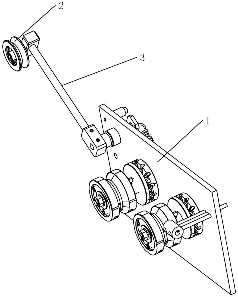
[0031] like Figure 1-7 As shown, the present invention includes a base 1 , an adjusting device arranged at one end of the base 1 , and a reverse buffering device arranged at the center of the base 1 .

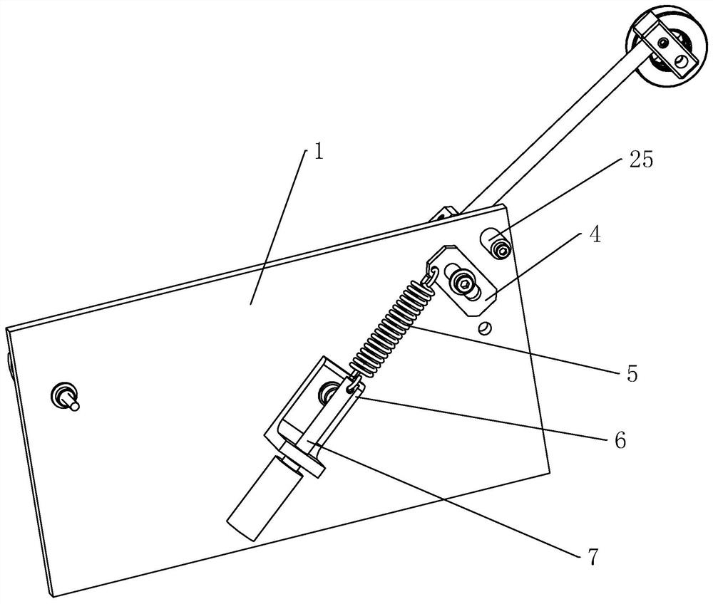
[0032] The adjusting device includes a pulley 2, a bridge rod 3 with a Z-shaped structure, a baffle plate 4, a tension spring 5, a fixed seat 6 and an electric cylinder 7 for adjusting the torsion moment of the tension spring 5; the pulley 2 is sleeved through a bearing. At one end of the bridging rod 3, the other end of the bridging rod 3 is co...


PUM


Abstract

The wire puller comprises a base, an adjusting device arranged at one end of the base and a reverse buffering device arranged in the center of the base, the adjusting device comprises a pulley, a bridging rod of a Z-shaped structure, a baffle, an extension spring, a fixing base and an electric air cylinder, the pulley is arranged at one end of the bridging rod through a bearing in a sleeving mode, and the baffle is arranged on the base. The electric air cylinder is arranged on the side, close to the baffle, of the base through a fixing base, and an air rod of the electric air cylinder is connected with the baffle through an extension spring. The reverse buffering device comprises a mounting base, a positioning shaft and a tensioning wheel, the positioning shaft is located on the side, close to the pulley, of the base, the tensioning wheel is arranged on the positioning shaft in a sleeving mode and connected with the mounting base through the positioning shaft, and the mounting base is located between the tensioning wheel and the base and inserted into the base; according to the rope winding device, when a rope is wound, the rope can be in a constant stress and tightening state all the time, and when encountering special situations, reverse buffering can be conducted immediately, so that the rope stops moving gradually.

Description

technical field [0001] The invention mainly relates to the field of cable winding and conveying, in particular to a wire puller used for a winding winding device. Background technique [0002] Ropes have the properties of tensile strength, impact resistance, wear resistance, flexibility, lightness and softness, and have been widely used in various fields of life. Even in some industries such as ships, logistics and heavy industry, some high-strength ropes have been Necessities, in recent years, with the development of society and the vigorous rise of the marine industry, the rope as a marine tool has become more and more important, and the rope can realize the towing and fixing of the ship. [0003] The existing rope structure and technology are relatively mature, but the users still found some problems during the long-term use. However, during the winding process, if the other end of the cable is not fixed, it will cause the cable to loosen during the winding process. [...

Claims


Application Information

Patent Timeline
Patent Type & Authority Applications(China)
IPC IPC(8): B65H59/10B65H59/18
CPCB65H59/10B65H59/18B65H2701/35
Inventor 苗锦雷
Owner JIANGSU HAIFENG ROPE TECH CO LTD
Why Eureka
Try Eureka