
Wave error prevention method for ultrasonic flowmeter and ultrasonic flowmeter

A flowmeter and ultrasonic technology, applied in the field of anti-error wave method and ultrasonic flowmeter, can solve the problems such as the change of the received signal of the transducer, the inability to guarantee the measurement accuracy, and the inability of the wrong wave to avoid the influence of the wrong wave and facilitate real-time calculation. , the effect of improving the measurement accuracy

Pending Publication Date: 2022-07-12
金卡水务科技有限公司
View PDF0 Cites 5 Cited by
  • Summary
  • Abstract
  • Description
  • Claims
  • Application Information

AI Technical Summary

Problems solved by technology

In the actual application scene of the ultrasonic flowmeter, there will be more interference, such as scaling on the surface of the transducer, more impurities, environmental noise, etc. The appearance of these ubiquitous and unavoidable interference will cause the transducer to receive The signal changes, which leads to the situation that the set threshold does not meet the measurement requirements and the wrong wave occurs
[0003] In the conventional ultrasonic measurement algorithm, the usual method is to abandon the value of the wrong wave measured this time and use the last measured value instead. Measurement errors are generated, which affect the accuracy of measurement
Therefore, this method can only perform short-term compensation and cannot guarantee its measurement accuracy, let alone solve the problem of wrong waves in principle

Method used


Image

  • Wave error prevention method for ultrasonic flowmeter and ultrasonic flowmeter
  • Wave error prevention method for ultrasonic flowmeter and ultrasonic flowmeter
  • Wave error prevention method for ultrasonic flowmeter and ultrasonic flowmeter

Examples


Embodiment Construction

[0049] Exemplary embodiments of the present disclosure will be described in more detail below with reference to the accompanying drawings. While exemplary embodiments of the present disclosure are shown in the drawings, it should be understood that the present disclosure may be embodied in various forms and should not be limited by the embodiments set forth herein. Rather, these embodiments are provided so that the present disclosure will be more thoroughly understood, and will fully convey the scope of the present disclosure to those skilled in the art.

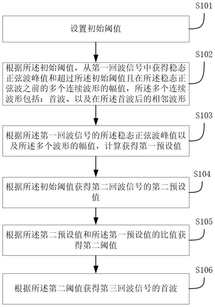
[0050] In a first aspect, according to an embodiment of the present application, an error-proofing method for an ultrasonic flowmeter is proposed, such as figure 1 shown, including:

[0051] S101, setting an initial threshold;

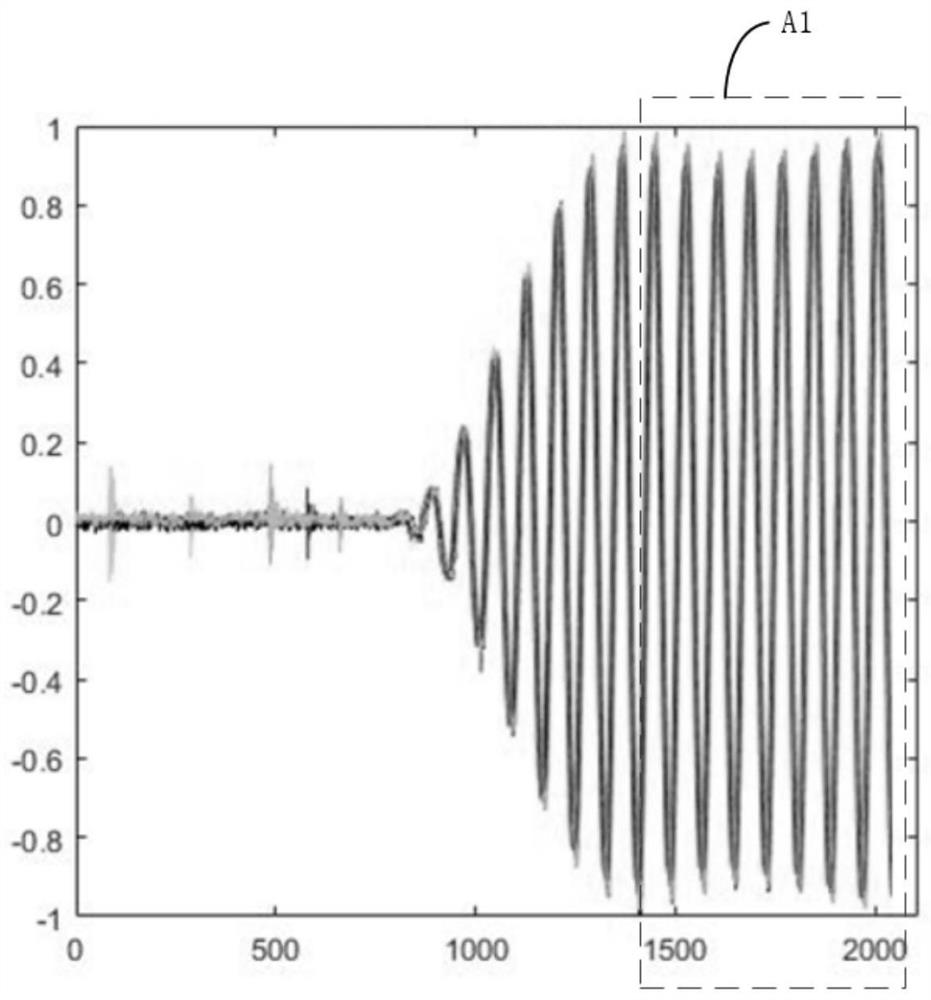
[0052] S102, according to the initial threshold, obtain from the first echo signal the peak value of the steady-state sine wave and the amplitudes of multiple continuous waveforms that exceed the i...


PUM


Abstract

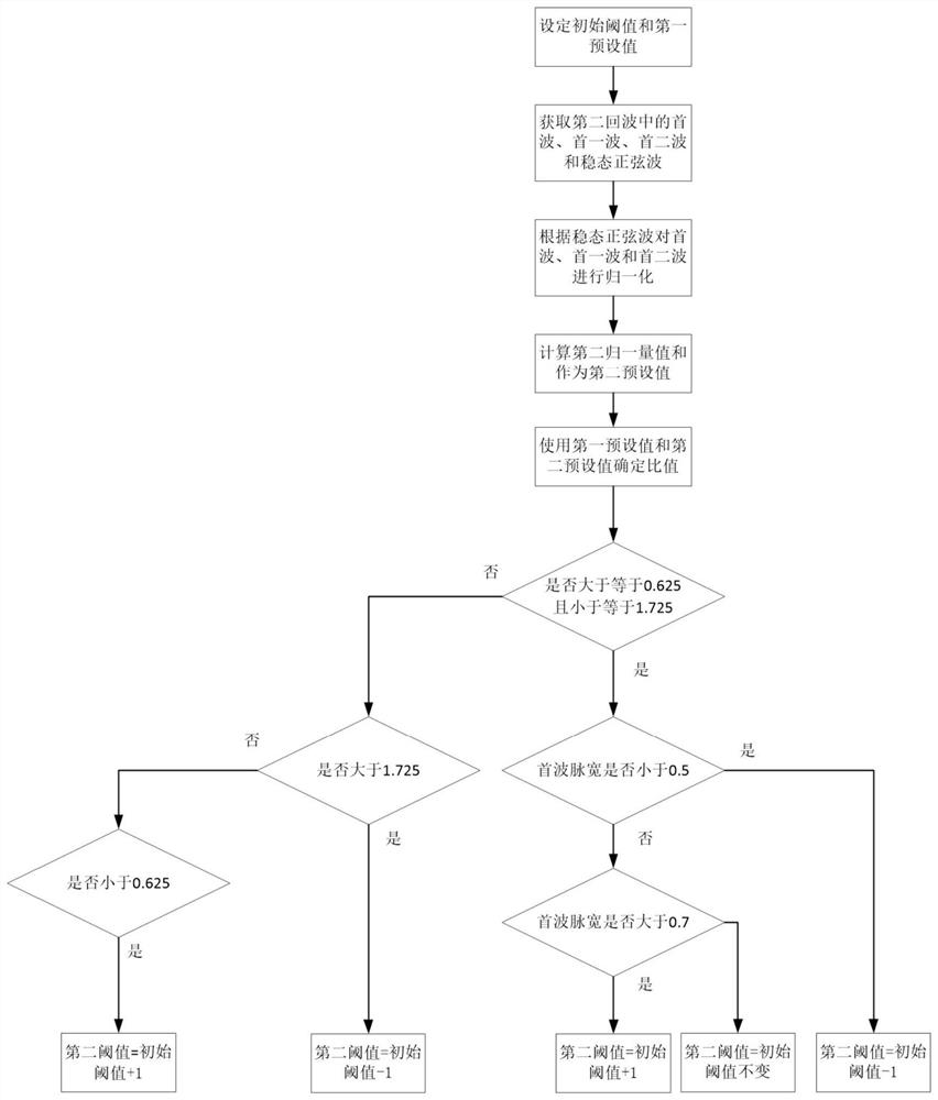
The invention discloses a wrong wave prevention method for an ultrasonic flowmeter and the ultrasonic flowmeter. The method comprises the steps that an initial threshold value is set; according to the initial threshold value, a steady-state sine wave peak value and amplitudes of a plurality of continuous waveforms which exceed the initial threshold value and are before the steady-state sine wave are obtained from the first echo signal, and the amplitudes comprise a head wave and an adjacent waveform after the head wave; according to the steady-state sine wave peak value of the first echo signal and the amplitudes of the plurality of waveforms, calculating to obtain a first preset value; obtaining a second preset value of the second echo signal according to the initial threshold value; obtaining a second threshold value according to the ratio of the second preset value to the first preset value; and obtaining the head wave of the third echo signal according to a second threshold value. The ratio of the first preset value of the first echo signal to the second preset value of the second echo signal is calculated, the initial threshold is adjusted according to the ratio to obtain the second threshold, logic is simple, real-time calculation is facilitated, the influence of wrong waves can be avoided, the influence of interference on a metering result is reduced, and metering precision is improved.

Description

technical field [0001] The present application relates to the technical field of ultrasonic instruments, and in particular, to an error-proofing method for an ultrasonic flowmeter and an ultrasonic flowmeter. Background technique [0002] In recent years, with the advancement of science and technology, smart water meters have developed rapidly. Ultrasonic flowmeters have gained more and more attention in the field of flow detection due to their advantages of large range ratio, small initial flow, low pressure loss, and bidirectional measurement. application. Ultrasonic flowmeters generally use the time difference method for measurement. The time difference method is a measurement method that calculates the flow information according to the propagation time difference of the ultrasonic waves in the measured medium under two conditions of forward flow and reverse flow. At present, in the time difference method, the accurate forward and reverse flight time is generally obtaine...

Claims


Application Information

Patent Timeline
Patent Type & Authority Applications(China)
IPC IPC(8): G01F1/667
CPCG01F1/66G01F1/662
Inventor 戴敏达于群
Owner 金卡水务科技有限公司
Learn More