Infrared touch screen device and multipoint locating method thereof

a multi-point locating and infrared technology, applied in the field of infrared touch screen technology, can solve the problems of poor practical effect, system error in providing wrong position coordinates deviating from the actual position, and failure of conventional infrared touch screen systems to work, so as to facilitate hardware speed up, accurate and reliable calculation, the effect of facilitating the speed up

Inactive Publication Date: 2012-08-30
SHANGHAI JINGYAN ELECTRONICS TECH
View PDF64 Cites 20 Cited by
  • Summary
  • Abstract
  • Description
  • Claims
  • Application Information

AI Technical Summary

Benefits of technology

[0031]2. The present disclosure provides a simple method to process all axes scanning information with simple logic, facilitating a speed up in hardware.
[0032]3. With the present method, it is easy, accurate and reliable to calculate the touch point position.

Problems solved by technology

In this way, the infrared touch-screen system can only detect one set of position coordinates in a preset time period, which means the infrared touch-screen system can work well when there is only one touch event happening, however, if there are multiple touch events happening in a preset time period, the system would make an error with providing wrong position coordinates deviating from the actual position.
For the above reasons, the conventional Infrared touch screen system fails to work in situations where a multiple touch events are required.
However, for multiple touch points moving simultaneously, or multiple touch points moving in intersection way, it happens frequently in practice that the position is misidentified, resulting in a poor practical effect.
CN200710100010.2 discloses a method by utilizing an off-axis scanning, that is, a skew axis scanning to get rid of false touch points, in which different axes are processed by different means, resulting in a complicated logic, and a complicated mathematical model especially with the increasing of the number of the touch points, which still results in poor practical effect.

Method used


Image

  • Infrared touch screen device and multipoint locating method thereof
  • Infrared touch screen device and multipoint locating method thereof
  • Infrared touch screen device and multipoint locating method thereof

Examples


Embodiment Construction

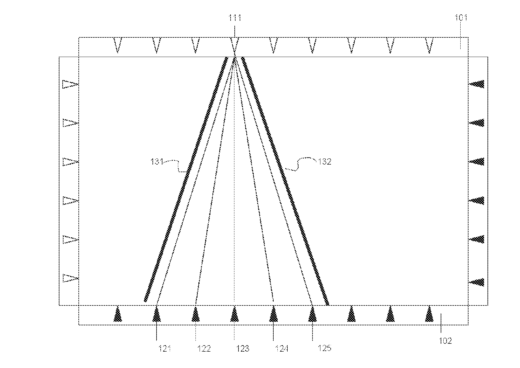
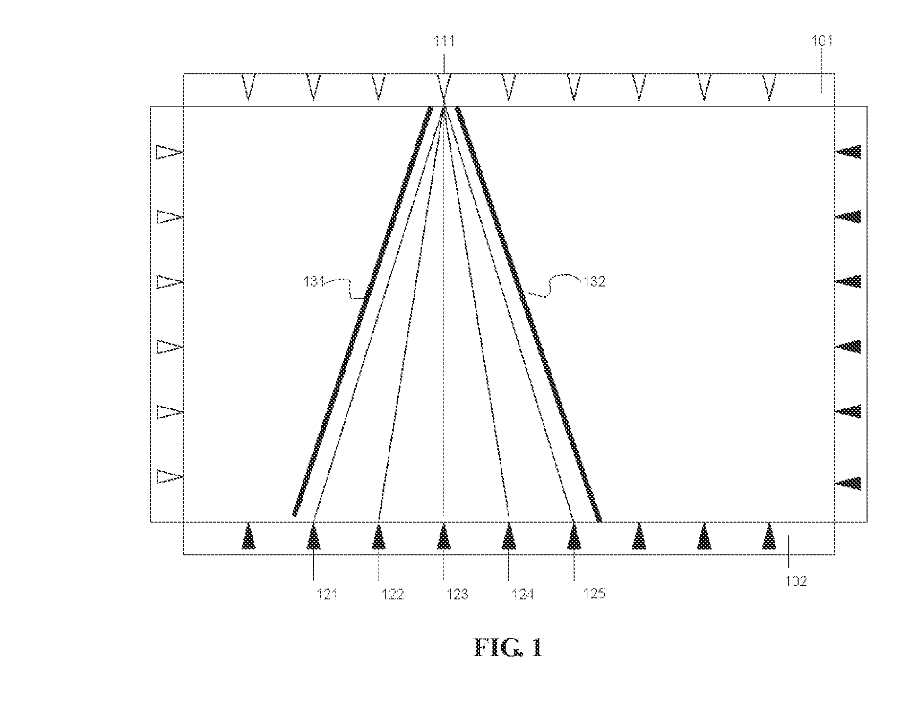
[0046]FIG. 1 is a schematic view for illustrating that infrared beams sent from an infrared transmission unit are detected by multiple infrared reception units according to an embodiment of the present disclosure. Referring to FIG. 1, an infrared touch screen device includes a transmission circuit board 101 equipped with infrared transmission units, and a reception circuit board 102 equipped with infrared reception units. An infrared transmission unit 111 is arranged on the transmission circuit board 101, and infrared reception units 121, 122, 123, 124 and 125 are arranged on the reception circuit board 102. Lines 131 and 132 show a transmission angle range of the infrared transmission unit 111. As shown in FIG. 1, infrared beams sent from the infrared transmission unit 111 can be detected by the infrared reception units 121, 122, 121 and 125.

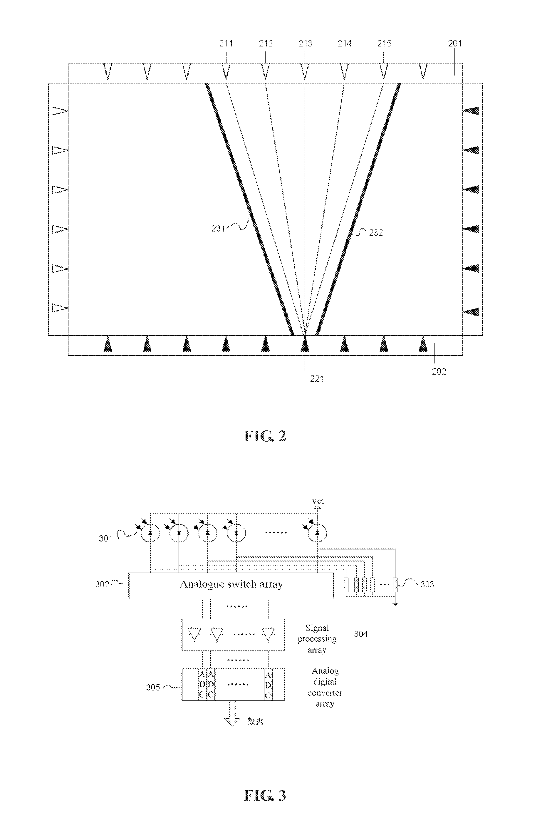
[0047]FIG. 2 is a schematic view for illustrating that an infrared reception unit receives infrared beams sent from multiple infrared transmis...


PUM


Abstract

An infrared touch screen device and a multi-touch locating method thereof are provided. On the touch screen, large angle infrared emitting elements and infrared receiving element are used to realize the axis scanning of multi-angle by an optimized sampling and processing circuit. After the data processing of removing ambient light, normalization and so on for original data of the axis scanning, the logic axis touch information is generated, and a luminance map of the current frame is generated according to the information. Multiple valid touch regions are recognized by contrast with a theoretical touch luminance map. Then a tracing algorithm of image is used, and a multi-touch event is outputted finally. The touch device is simple, reliable and accurate and has wide range application.

Description

CROSS REFERENCE TO RELATED APPLICATIONS[0001]The present application claims priority to Chinese Patent Application No. 200910198341.3, entitled “INFRARED TOUCH SCREEN DEVICE AND MULTIPOINT LOCATING METHOD THEREOF”, and filed on Nov. 5, 2009, the entire disclosure of which is incorporated herein by reference.FIELD OF THE INVENTION[0002]The present invention generally relates to the infrared touch screen technology, and more particularly, to an infrared touch screen device which is capable of distinguishing multiple touch points and operating the multiple points at the same time, and a method for positioning multiple touch points thereof.BACKGROUND OF THE INVENTION[0003]Infrared touch screen devices have been developed rapidly as an interactive device because of simple production process and low production cost. A fundamental structure of an infrared touch screen device includes a plurality of pairs of infrared transmission and reception units arranged along the edges of a display in ...

Claims


Application Information

Patent Timeline
Patent Type & Authority Applications(United States)
IPC IPC(8): G06F3/042
CPCG06F2203/04104G06F3/0421
Inventor ZHAO, LEIZHANG, YUMING
Owner SHANGHAI JINGYAN ELECTRONICS TECH
Why Eureka
Try Eureka