Front magnifier and imaging device

A magnifying mirror and lens technology, applied in the optical field, can solve the problems of increasing field of view angle requirements, higher zoom ratio requirements, and reduced video resolution, achieving miniaturization and increasing light throughput. , lens smoothing effect

Pending Publication Date: 2022-07-12
JIAXING ZHONGRUN OPTICAL TECH
View PDF0 Cites 0 Cited by
  • Summary
  • Abstract
  • Description
  • Claims
  • Application Information

AI Technical Summary

Problems solved by technology

[0003] However, in the process of network transmission and digital zooming, the clarity (that is, resolution) of the video will decrease to a certain extent, but at the same time, people's requirements for image resolution are getting higher and higher. The requirements for the field of view are getting bigger and bigger, and the requirements for the zoom ratio are also higher. Therefore, a multiplier is added to the existing lens to make the lens meet the higher requirements of customers.
[0004] Existing multipliers are usually large in size, and at the same time, in order to reduce the volume of the multiplier, the volume of the multiplier can only be reduced by using a large number of aspheric surfaces, thus greatly increasing the cost of the multiplier. The use of aspheric surface will bring about the reduction of image quality

Method used


Image

  • Front magnifier and imaging device
  • Front magnifier and imaging device
  • Front magnifier and imaging device

Examples


Embodiment 1

[0062] like figure 1 , 2 As shown in Fig. 8, a pre-multiplier mirror G1, the front-end multiplier G1 sequentially includes from the object plane side to the image plane side:

[0063] a first lens group g1 with negative refractive power and a second lens group g2 with positive refractive power;

[0064] The lenses in the front multiplier G1 are all composed of spherical lenses;

[0065] The front multiplier G1 only includes one set of cemented lenses.

[0066] In this embodiment, the setting of the spherical lens greatly reduces the cost of the pre-converter G1, and at the same time, by limiting the number of cemented lenses, the use of aspheric surfaces is reduced, and the cost of the multiplier G1 is reduced; While increasing the image quality of the main lens G2 that can be adapted, it will not greatly increase the cost of the extender G1, and at the same time, it will not affect the volume of the extender G1 due to the large imaging effect. The image quality of the mai...

Embodiment 2

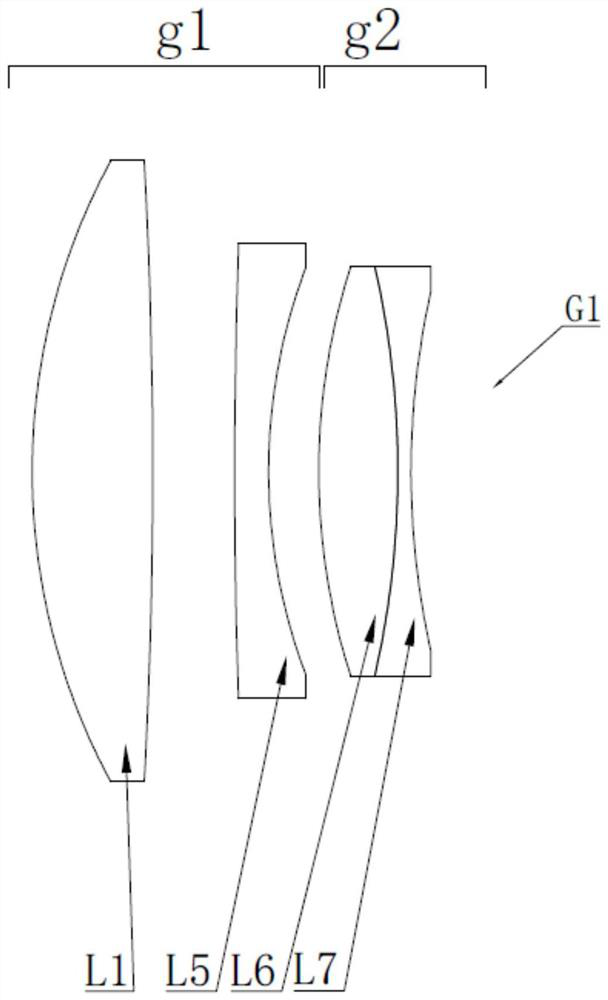
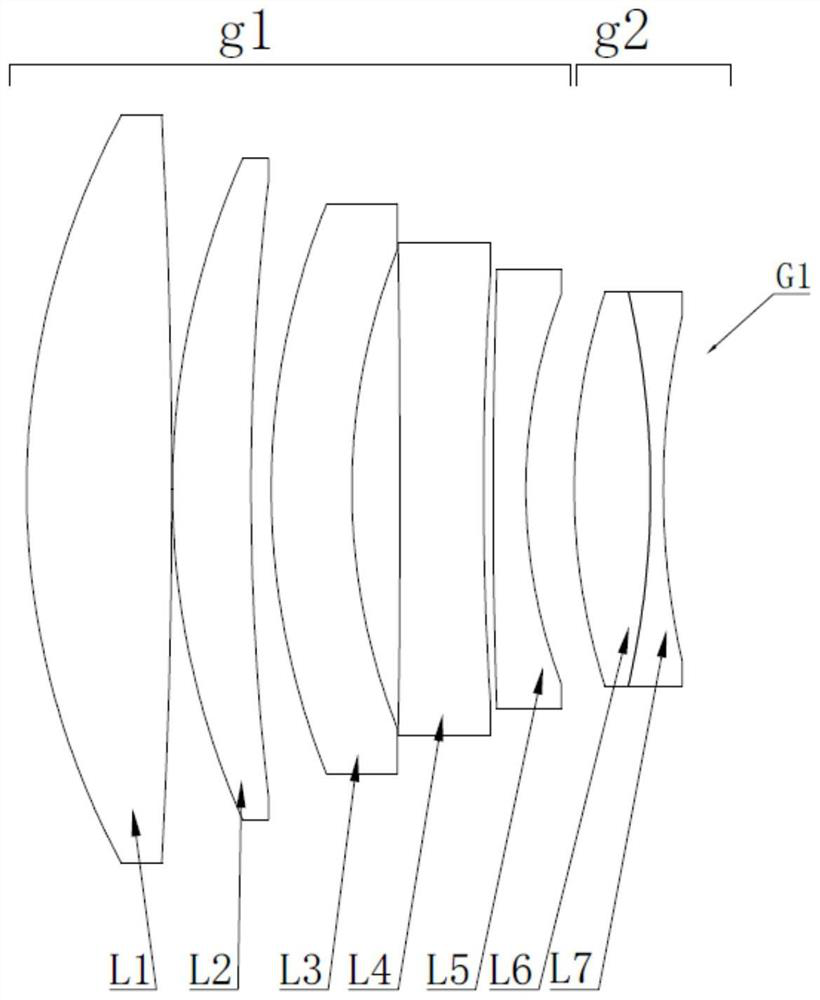
[0076] like figure 2 and 8 As shown, on the basis of Embodiment 1, in this embodiment, the first lens group g1 consists of a first lens L1 with positive refractive power, a second lens L2 with positive refractive power, a third lens L3 with negative refractive power, The fourth lens L4 with negative refractive power and the fifth lens L5 with negative refractive power are composed.

[0077] Or the first lens group g1 is composed of a first lens L1 with positive refractive power, a second lens L2 with positive refractive power, a third lens L3 with negative refractive power, and a fifth lens L5 with negative refractive power.

[0078] The second lens L2 and the third lens L3 are both meniscus lenses, and both the second lens L2 and the third lens L3 are curved toward the object surface side.

[0079] In this embodiment, the angle of light entering the second lens group g2 is further adjusted through the second lens L2 and the third lens L3, thereby increasing the imaging qua...

Embodiment 3

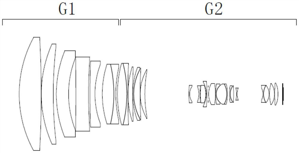
[0097] like Figure 2 to Figure 7 As shown, an imaging device, from the object plane side to the image plane side, includes:

[0098] Front extender G1;

[0099] main lens G2;

[0100] and an imaging element configured to receive the image formed by the main lens G2.

[0101] The front magnifier G1 includes sequentially from the object plane side to the image plane side:

[0102] a first lens group g1 with negative refractive power and a second lens group g2 with positive refractive power;

[0103] The first lens group g1 consists of a first lens L1 with positive power, a second lens L2 with positive power, a third lens L3 with negative power, a fourth lens L4 with negative power, and a fourth lens L4 with negative power. It consists of five lenses L5.

[0104] The second lens group g2 includes sequentially from the object plane side to the image plane side:

[0105] The sixth lens L6 of positive refractive power and the seventh lens L7 of negative refractive power are c...


PUM


Abstract

The invention relates to the field of optics, in particular to a front zoom lens and an imaging device. The front zoom lens is composed of a first lens group with negative focal power and a second lens group with positive focal power from the object plane side to the image plane side. Lenses in the front magnifying lens are all composed of spherical lenses. And the front magnifying lens only comprises a group of balsaming lenses. According to the zoom lens, the cost of the zoom lens is not greatly increased while the imaging quality of the adaptive main lens is improved, meanwhile, the size of the zoom lens is not influenced by large imaging, the miniaturization of the zoom lens is realized, and the imaging quality of the main lens is improved.

Description

technical field [0001] The invention relates to the field of optics, in particular to a front magnifying mirror and an imaging device. Background technique [0002] With the development of science, the security market is constantly improving. With the continuous maturity of advanced video compression and coding technology, the rapid development of IP-based network transmission and the application of digital zoom technology, 4k / 8k resolution ultra-high-definition cameras have been launched on the market. [0003] However, in the process of network transmission and digital zooming, the definition (ie resolution) of the video will decrease to a certain extent, but at the same time, people's requirements for image resolution are getting higher and higher. The requirements for the angle of view are also increasing, and the requirements for the zoom ratio are also higher, so the existing lens is equipped with a multiplier to make the lens meet the higher requirements of customers...

Claims


Application Information

Patent Timeline
Patent Type & Authority Applications(China)
IPC IPC(8): G02B15/10G02B15/14G02B15/177G02B13/00G02B27/00
CPCG02B15/10G02B15/1425G02B15/177G02B13/005G02B13/006G02B27/0025
Inventor 黄羿詹卫民胡晓戴殷杰
Owner JIAXING ZHONGRUN OPTICAL TECH
Why Eureka
Try Eureka