
Eureka
For R&D, Eureka makes reading and utilizing patents & technical documents easy.
Eureka AIR
Designed for self-driven R&D workflows. Generate viable solutions, solve complex R&D challenges, empower your innovation with AI.

Eureka Materials
Designed for material experts only. Revolutionize your material R&D, from search, analyze, to developing new materials.

TechResearch
Generate reliable direction feasibility study reports for your R&D in just a few steps.

TechSeek
Discover and master advanced knowledge NOW. Basics, ideas, possibilities, all at once.

TechMind
As an expert in R&D Theories, TechMind can generates customized viable solutions instantly.

TechRisk
Analyze your overall solution with one click, know your potential R&D risks in advance.

TechMonitor
Get weekly tech updates, stay abreast of the latest tech innovations and key insights.
Method and control circuitry for operating autonomous feed robot at feed station in livestock zone
A technology for controlling a circuit and a feeding table, which is applied in the field of computer programs and can solve problems such as failure to provide a feeding table in real time.
- Summary
- Abstract
- Description
- Claims
- Application Information
AI Technical Summary
Problems solved by technology
Method used
Image

Examples
Embodiment Construction
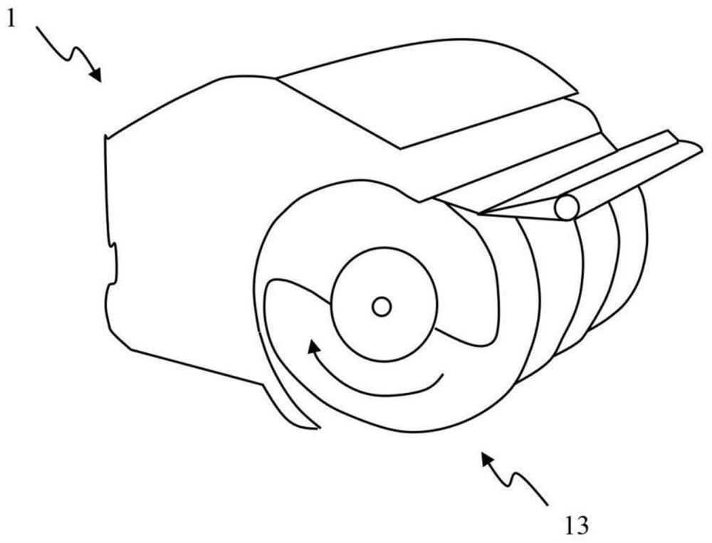
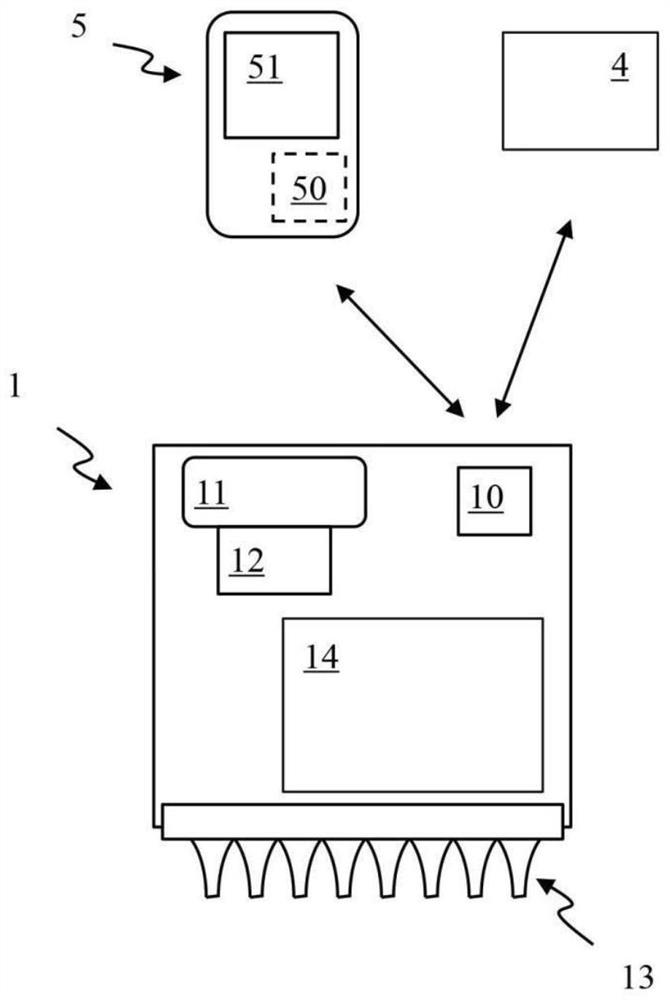
[0030] Visual identification technology is becoming more common, reliable and inexpensive. Visual recognition technology refers to the technology of analyzing and understanding the content of an image. Visual recognition in a barn can be used to improve operational efficiency and affect energy consumption in different ways. The present disclosure is based on the idea of having a camera system installed in the livestock area where the autonomous feeding robot works. The cameras are arranged to capture images revealing the distribution of the feed present at the feeding table. The image may, for example, be used to enable the autonomous feeding robot to operate only when it is really needed, rather than based on a user guessed or otherwise predefined schedule. Therefore, this paper proposes to implement visual recognition technology in livestock areas in order to operate an autonomous feeding robot to autonomously adjust its operation based on the current distribution of fee...
PUM
 Abstract
Description
Claims
Application Information
 - R&D Engineer
- R&D Manager
- IP Professional
- Industry Leading Data Capabilities
- Powerful AI technology
- Patent DNA Extraction
Browse by: Latest US Patents, China's latest patents, Technical Efficacy Thesaurus, Application Domain, Technology Topic, Popular Technical Reports.
© 2024 PatSnap. All rights reserved.Legal|Privacy policy|Modern Slavery Act Transparency Statement|Sitemap|About US| Contact US: help@patsnap.com