

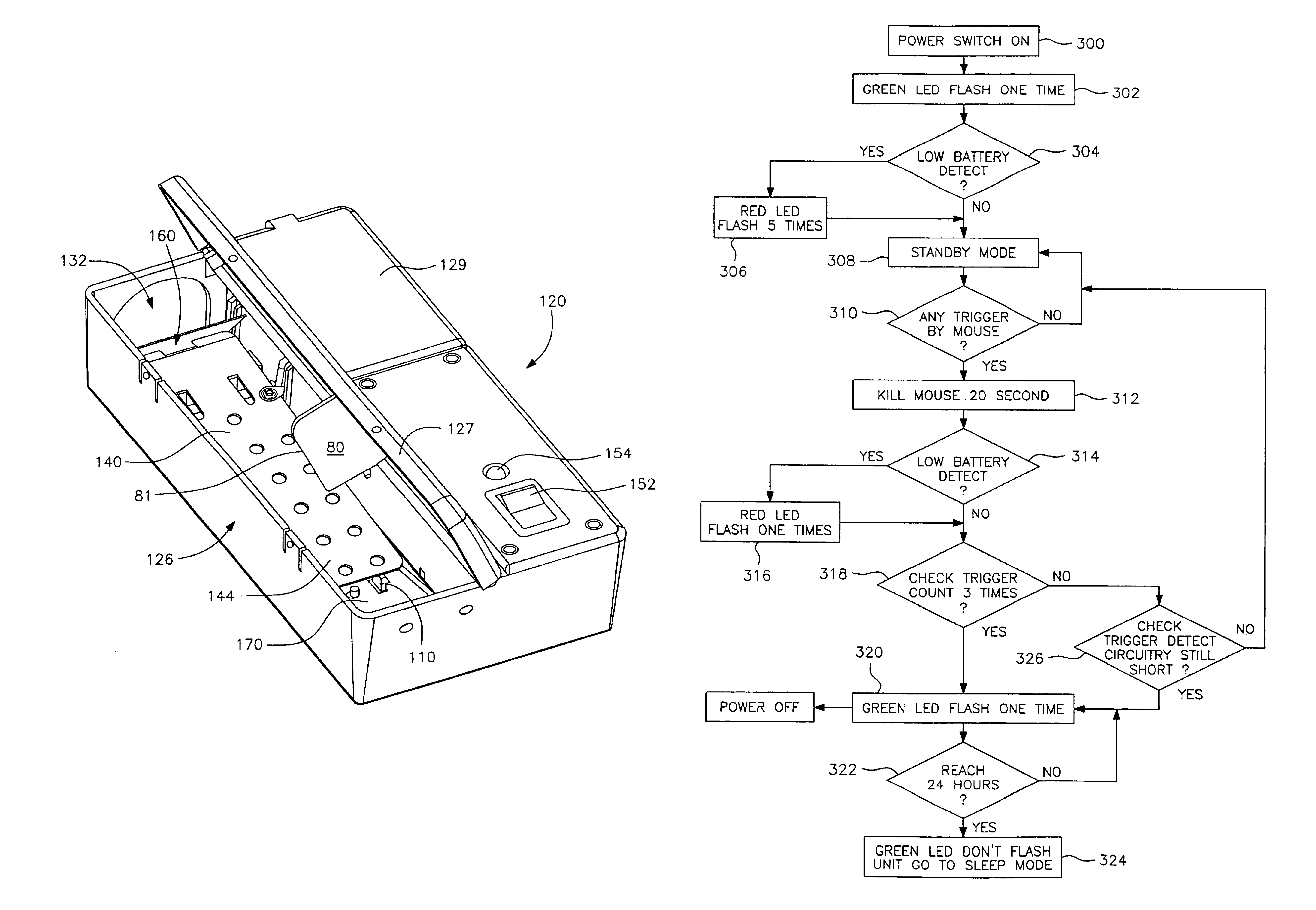
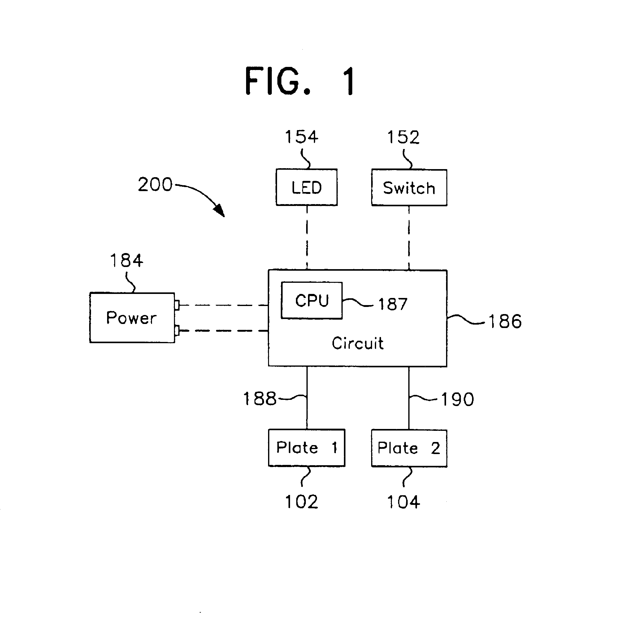
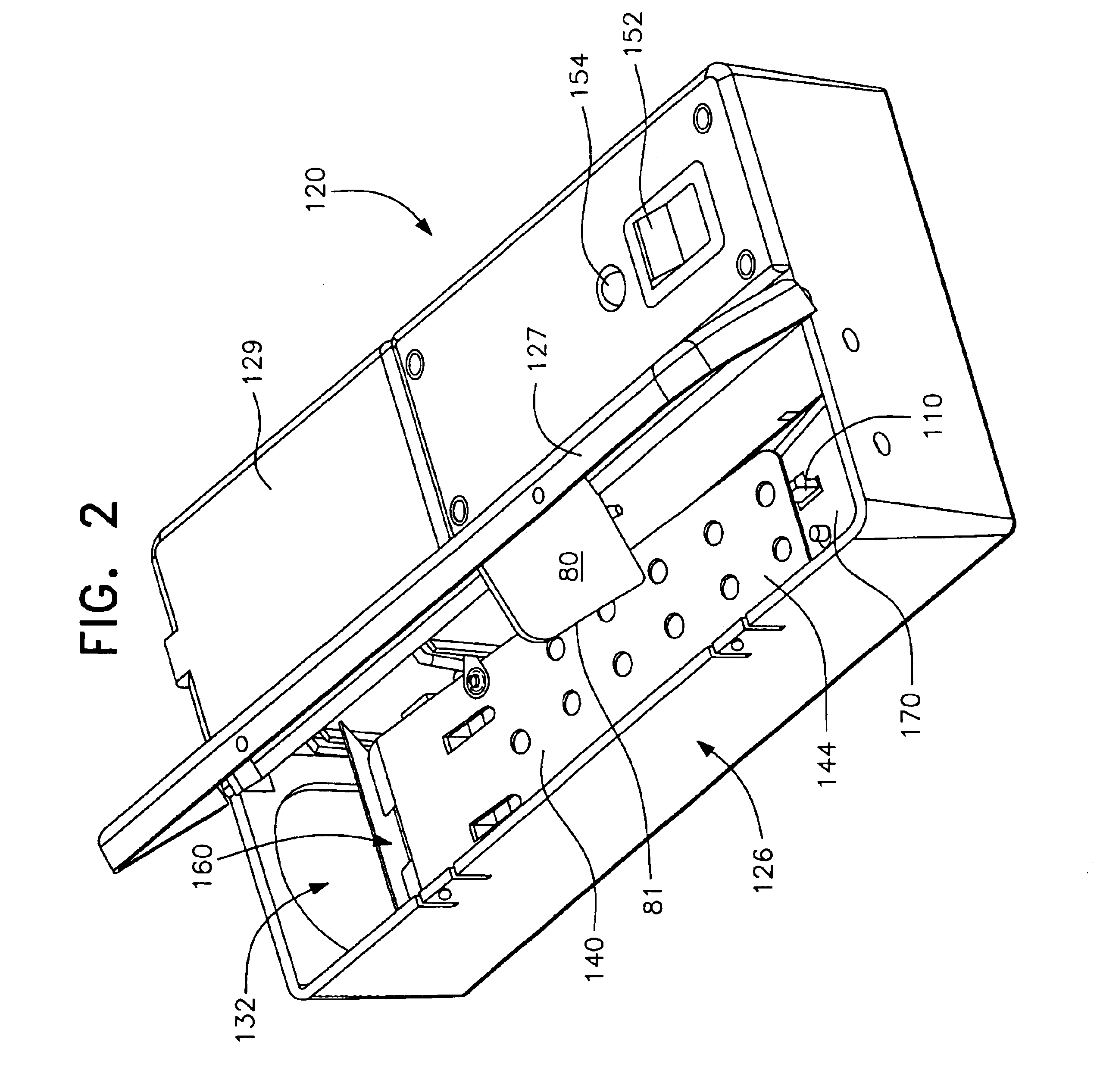
CPU-controlled, rearming, high voltage output circuit for electronic animal trap
a high-voltage output circuit and electronic animal trap technology, applied in the field of electric or electronic animal traps, can solve the problems of limiting the ability of the captured animal to return to the passageway, complicated structures which are costly to manufacture, and traps are not conveniently employed without disruption of the animal's environment, so as to reduce the service requirements
- Summary
- Abstract
- Description
- Claims
- Application Information
AI Technical Summary
Benefits of technology
Problems solved by technology
Method used
Image

Examples
Embodiment Construction
Although only a few preferred embodiments of the invention are explained in detail, it is to be understood that other embodiments are possible and likely. Accordingly, it is not intended that the invention is to be limited in its scope to the details of construction and arrangement of components set forth in the following description or illustrated in the drawings. The invention is capable of other embodiments and of being practiced or carried out in various ways. Also, in describing the preferred embodiments, specific terminology will be resorted to for the sake of clarity. It is to be understood that each specific term includes all technical equivalents which operate in a similar manner to accomplish a similar purpose.
Although the concepts of the instant invention are equally applicable to traps for animals of any size, devices of this type are primarily utilized in connection with the trapping of rodents such as mice and rats and, therefore, further discussion herein will be prim...
PUM
 Abstract
Description
Claims
Application Information