Staples for generating and applying compression within a body

a technology of compression and staples, applied in the field of surgical staples, can solve the problems of slowing down the healing process, affecting healing, and disrupting the healing tissu

Active Publication Date: 2016-07-14
ARTHREX
View PDF1 Cites 62 Cited by
  • Summary
  • Abstract
  • Description
  • Claims
  • Application Information

AI Technical Summary

Benefits of technology

[0016]The present invention provides a novel fixation device which is able to bring bone fragments into close proximity with each othe

Problems solved by technology

Furthermore, gaps between bone fragments that are too large allow motion to occur between the bone fragments, disrupting the healing tissue and thus slowing the healing process.
In addition, the action of tamping can cause the bone fragments to move out of position, impairing healing.
Furthermore, current staple systems do not allow the surgeon to control the amount of compression that the staple will exert when it is released from the delivery device.
While the shape memory and superelastic properties allow Nitinol staples to pull together the opposing bone fragments, the recovery forces and recoverable strain generated by these staples may be too great and may result in the staples “tearing through” the bone tissue and thus not providing a means to generate and maintain compression between the bone fragments.
Additionally, current staple systems do not allow the surgeon to control the rate at which the staple loads the bone when it is removed from the delivery device.
This may result in a large force impulse as the staple's legs rapidly undergo

Method used


Image

  • Staples for generating and applying compression within a body
  • Staples for generating and applying compression within a body
  • Staples for generating and applying compression within a body

Examples


example

[0103]The compressive force generated by staples of the present invention formed out of Nitinol with greater than 20% cold work are able to generate 50 to 100 Newtons of force depending on the staple dimensions. This is more than twice the compression force able to be generated by conventional staples of a similar size.

Alternative Configurations of Novel Staple Formed in Accordance with the Present Invention

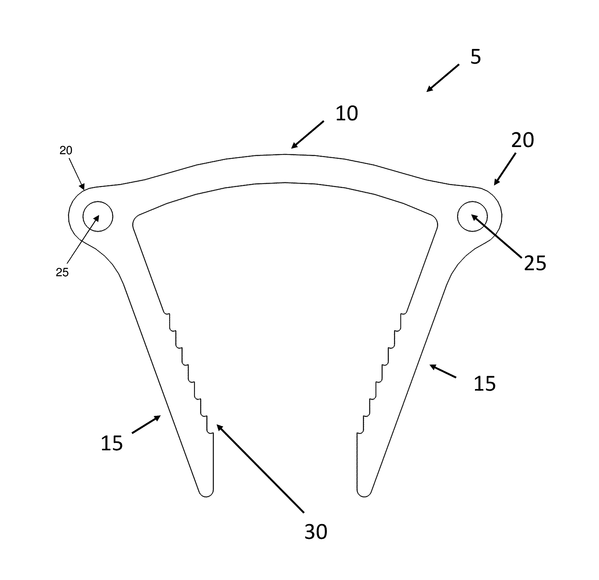
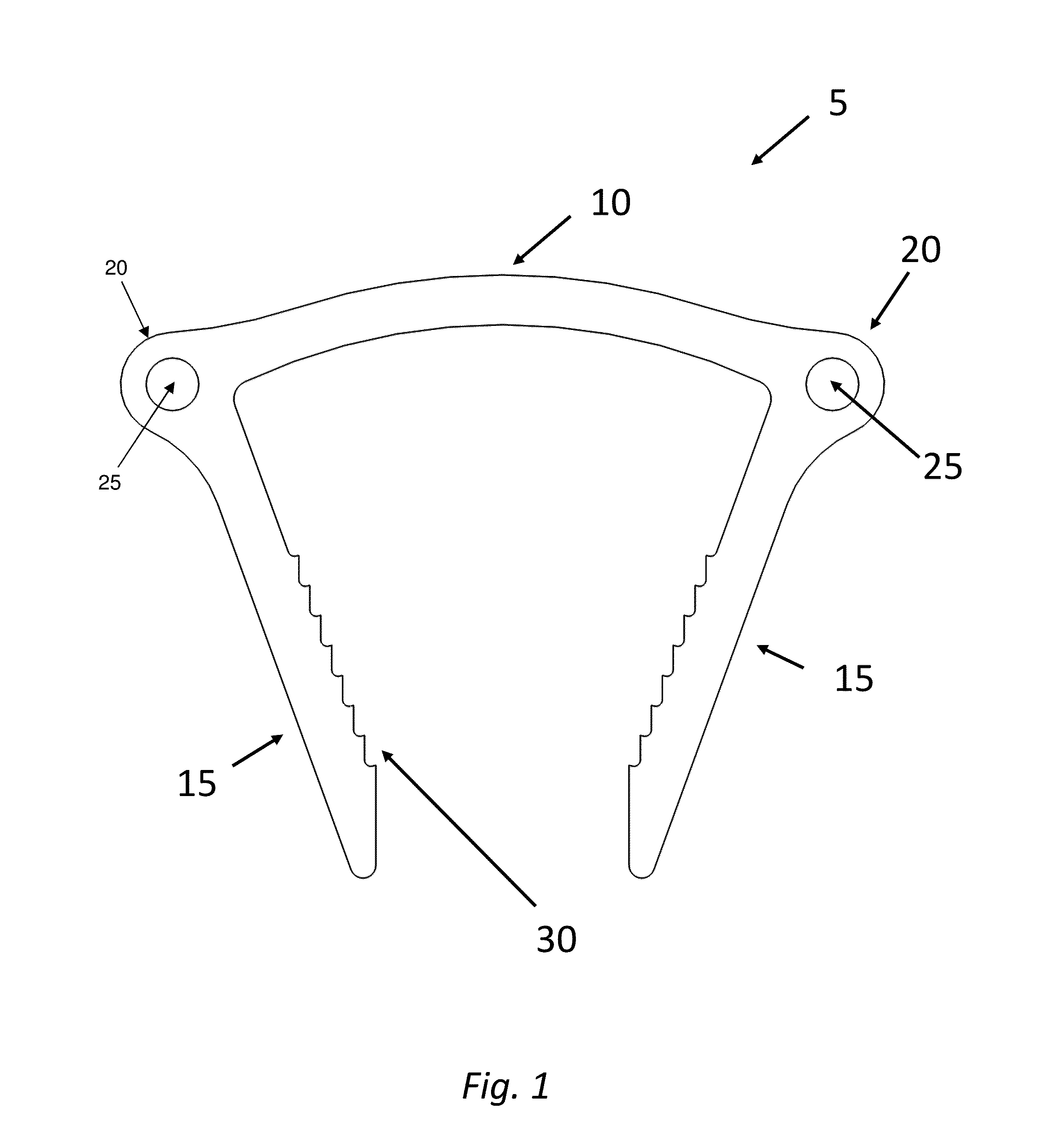
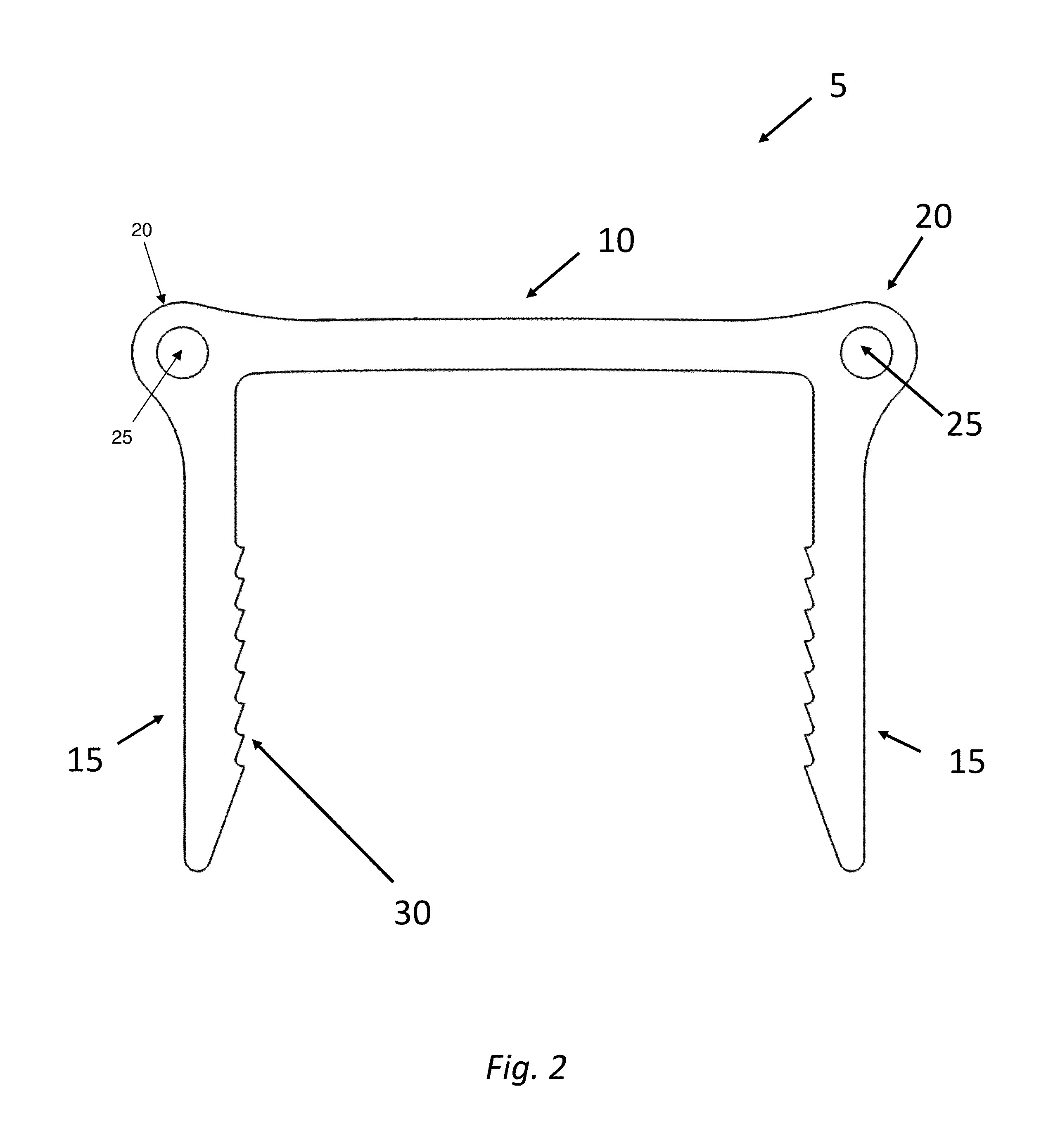
[0104]Looking now at FIGS. 11-19 it should be appreciated that staple bridge 10 may be formed so as to have a different configuration. By way of example but not limitation, it may be beneficial for staple bridge 10 to have a concave geometry (FIGS. 11-13), such that when bridge 10 of staple 5 is reversibly bent (i.e., so that legs 15 are pivoted so that they are parallel to each other), bridge 10 can bend downwardly, i.e., so as to become more concave (FIG. 12). Upon insertion of the strained staple 5 across the prepared fracture site, the constraint on bridge 10 and hinges 20 is...


PUM

PropertyMeasurementUnit
Forceaaaaaaaaaa
Shape memory effectaaaaaaaaaa

Abstract

Apparatus for generating, applying and maintaining compression to a site in a human or animal body, the apparatus comprising: a staple comprising: a bridge configured to be elastically bendable; a first leg connected to the bridge by a first hinge region configured to be elastically bendable; and a second leg connected to the bridge by a second hinge region configured to be elastically bendable; wherein the first hinge region comprises a first hole configured to mate with a first element of a delivery device and the second hinge region comprises a second hole configured to mate with a second element of a delivery device; and wherein the first and second legs are angled toward one another when they are in an unstrained state; whereby, when the staple is mounted to a delivery device so that the first hole of the first hinge region mates with a first element of a delivery device and the second hole of the second hinge region mates with a second element of a delivery device, and when the delivery device applies a force to the bridge of the staple so as to reconfigure the bridge of the staple, the first and second legs are pivoted away from one another toward a parallel disposition.

Description

REFERENCE TO PENDING PRIOR PATENT APPLICATIONS[0001]This patent application:[0002](i) is a continuation-in-part of pending prior U.S. patent application Ser. No. 14 / 540,351, filed Nov. 13, 2014 by MX Orthopedics, Corp. and Matthew Palmer et al. for STAPLES FOR GENERATING AND APPLYING COMPRESSION WITHIN A BODY (Attorney's Docket No. FONTE-52);[0003](ii) claims benefit of pending prior U.S. Provisional Patent Application Ser. No. 62 / 137,496, filed Mar. 24, 2015 by MX Orthopedics, Corp. and Daniel Morgan et al. for STAPLES THAT DO NOT NEED TO BE TAMPED TO BE FULLY SEATED FOR GENERATING AND APPLYING COMPRESSION WITHIN A BODY (Attorney's Docket No. FONTE-55 PROV);[0004](iii) claims benefit of pending prior U.S. Provisional Patent Application Ser. No. 62 / 137,570, filed Mar. 24, 2015 by MX Orthopedics, Corp. and Daniel Morgan et al. for STAPLES THAT DO NOT NEED TO BE TAMPED TO BE FULLY SEATED FOR GENERATING AND APPLYING COMPRESSION WITHIN A BODY (Attorney's Docket No. FONTE-56 PROV); and[0...

Claims


Application Information

Patent Timeline
IPC IPC(8): A61B17/064A61B17/068
CPCA61B17/0642A61B17/068A61B2017/0641A61B2017/0645A61B2017/00867A61B17/0682A61B17/10
Inventor MORGAN, DANIELPALMER, MATTHEWFONTE, MATTHEWDEVANEY, ROBERTNEALON, KAITLYNDELMONACO, ALEXANDER
Owner ARTHREX
Why Eureka
Try Eureka