Vacuum mixer

A vacuum mixer and mixer technology, applied in kitchen utensils, home utensils, applications, etc., can solve the problems of inconvenient use, inability to reverse the inner cylinder smoothly, etc., and achieve the goal of increasing torque, maximizing dehydration effect, and increasing rotation speed Effect

Pending Publication Date: 2022-07-12
因特薄有限公司
View PDF1 Cites 0 Cited by
  • Summary
  • Abstract
  • Description
  • Claims
  • Application Information

AI Technical Summary

Problems solved by technology

[0005] However, as disclosed in Korean Patent Publication No. 10-1772862, the above-mentioned agitator has a protrusion formed on the inner cylinder of the agitator, and since the object to be stirred in the inner cylinder rotates with the rotation of the pulverizing blade and is stuck on the protrusion, In the direction opposite to the rotation direction of the crushing blade, the reverse rotation of the inner cylinder will not be carried out smoothly. In particular, when the power of the inner cylinder driving motor is low, there is a limit that the inner cylinder does not reverse at all.
[0006] Further, even if the object to be stirred is crushed, in order to extract the juice and eat it, it is necessary to use a separate juice extractor to squeeze the juice, so it is not convenient to use

Method used


Image

  • Vacuum mixer
  • Vacuum mixer
  • Vacuum mixer

Examples


Embodiment Construction

[0034] Hereinafter, the present invention will be described in detail with reference to the accompanying drawings. It should be noted that when reference numerals are added to components in each drawing, the same components are given the same reference numerals as much as possible, even if indicated on different drawings. Also, in describing the present invention in detail, if a detailed description of a related known structure or function is considered to deviate from the gist of the present invention, the detailed description thereof will be omitted.

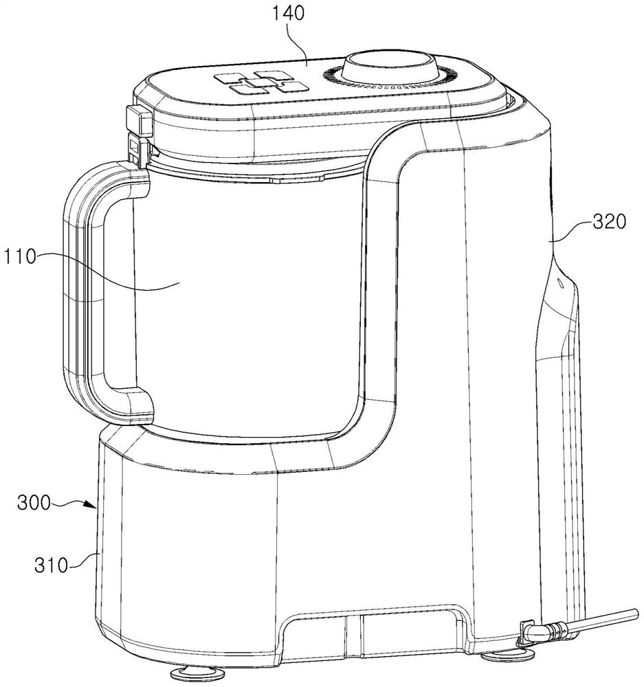
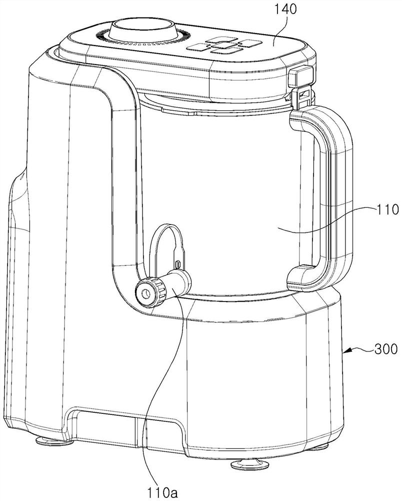
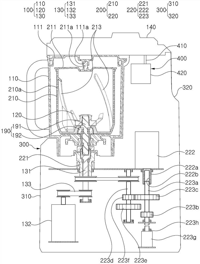
[0035] figure 1 and figure 2 is a perspective view showing a vacuum mixer according to the present invention, image 3 is a diagram showing the inside of a vacuum mixer according to an embodiment of the present invention, Figure 4 and Figure 5 is shown image 3 Diagram of the operating state of the inner cylinder drive part of the medium vacuum mixer.

[0036] Referring to the accompanying drawings, a vacuum mixer acc...


PUM


Abstract

The vacuum mixer according to the present invention comprises: a mixer main body including a cylinder support housing, an outer cylinder placed on the cylinder support housing, a crushing blade, and a blade driving part for rotating the crushing blade; the inner cylinder unit comprises an inner cylinder and an inner cylinder driving part, the inner cylinder is arranged in the outer cylinder, the crushing blades are located in the inner cylinder, and the inner cylinder driving part is used for rotating the inner cylinder; and a vacuum unit installed on the cartridge support housing and configured to perform a stirring operation on an object to be stirred accommodated inside the inner cartridge in a vacuum state, the outer cartridge being opened and closed by an outer cartridge cover, the inner cartridge being opened and closed by an inner cartridge cover, and the inner cartridge cover being rotatably assembled on the outer cartridge cover, a blade rotating shaft of the blade driving part is axially and rotatably mounted in a center hole formed in an inner cylinder rotating shaft of the inner cylinder driving part so that the blade rotating shaft and the inner cylinder rotating shaft axially rotate independently of each other, and an intermediate rotating shaft unit is provided in the outer cylinder, the intermediate rotating shaft unit connects the blade driving part and the pulverizing blade, and connects the inner cylinder driving part and the inner cylinder.

Description

technical field [0001] The invention relates to a vacuum mixer, in particular to a vacuum mixer for stirring objects to be stirred to squeeze juice. Background technique [0002] Generally, a blender is an electric device composed of a container (cup) for placing an object to be blended, and a main body containing a motor inside. [0003] Wherein, the container is made of hard heat-resistant glass, synthetic resin or stainless steel, and in the lower part of the container, the stainless steel pulverizing blade is matched and installed with the driving part. [0004] In addition, according to the high-speed rotation of the motor housed in the main body, it is not only used for cutting and pulverizing the stirring object including fruits, vegetables, etc., but also widely used in households to squeeze the stirring object. used. [0005] However, as disclosed in Korean Patent Gazette No. 10-1772862, the above-mentioned mixer has protrusions formed on the inner barrel of the m...

Claims


Application Information

Patent Timeline
IPC IPC(8): A47J44/00A47J43/08A47J43/07
CPCA47J43/0716A47J43/0727A47J43/087A47J44/00
Inventor 李杰柱
Owner 因特薄有限公司
Why Eureka
Try Eureka