Water and fertilizer applying device and method for soilless turf
An application device and technology for soilless turf, applied in the field of soilless turf water and fertilizer application devices, can solve the problems of poor spraying effect, loss, directly falling into the soil, etc., achieve good spraying effect, reduce waste, increase The effect of the sprayed area
- Summary
- Abstract
- Description
- Claims
- Application Information
AI Technical Summary
Problems solved by technology
Method used
Image

Examples
Embodiment 1
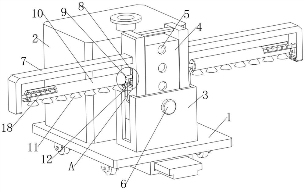
[0035] By sliding the sliding block 23 downward, the sliding block 23 drives the connecting rod 9 and the sliding sleeve 10 to slide downward, so that the sprinkler head 11 is close to the lawn, so as to achieve a good spraying effect. One end slides the slider 23, so that the slider 23 drives the connecting rod 9 and the sprinkler head 11 to slide to one end, and then moves the turf through the sprinkler head 11, so that the water and fertilizer sprayed by the sprinkler head 11 can flow along the blades of grass to the roots of the turf , so as to reduce the waste of water and fertilizer, and the spraying effect is good, please refer to Figure 1-3 , a water and fertilizer application device and method for soilless turf, wherein a water and fertilizer application device for soilless turf comprises a base 1 and a water tank 2 on the base 1, a support sleeve 3 is installed on the base 1, and the support sleeve 3 is connected with an adjustment Box 4, an extension plate 7 is ins...
Embodiment 2
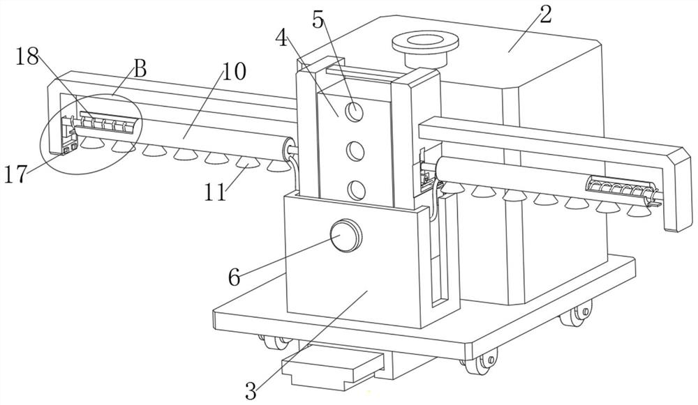
[0040] The spray head 11 is sprayed by centrifugal rotation, so as to increase the sprayed area. This embodiment is an improvement made on the basis of Embodiment 1. For details, please refer to Figure 1-5 The shower head 11 is rotatably connected to the sliding sleeve 10 , a gear 22 is installed on the shower head 11 , and a rack 21 is slidably connected inside the sliding sleeve 10 , and the rack 21 is used to drive the shower head 11 to slide.
[0041] Rotary spray: according to Figure 5 As shown, by sliding the rack 21 to the left, the rack 21 drives the gear 22 to rotate, and the gear 22 drives the sprinkler head 11 to rotate, so that the sprinkler head 11 sprays through centrifugal rotation, thereby increasing the spraying area.
Embodiment 3
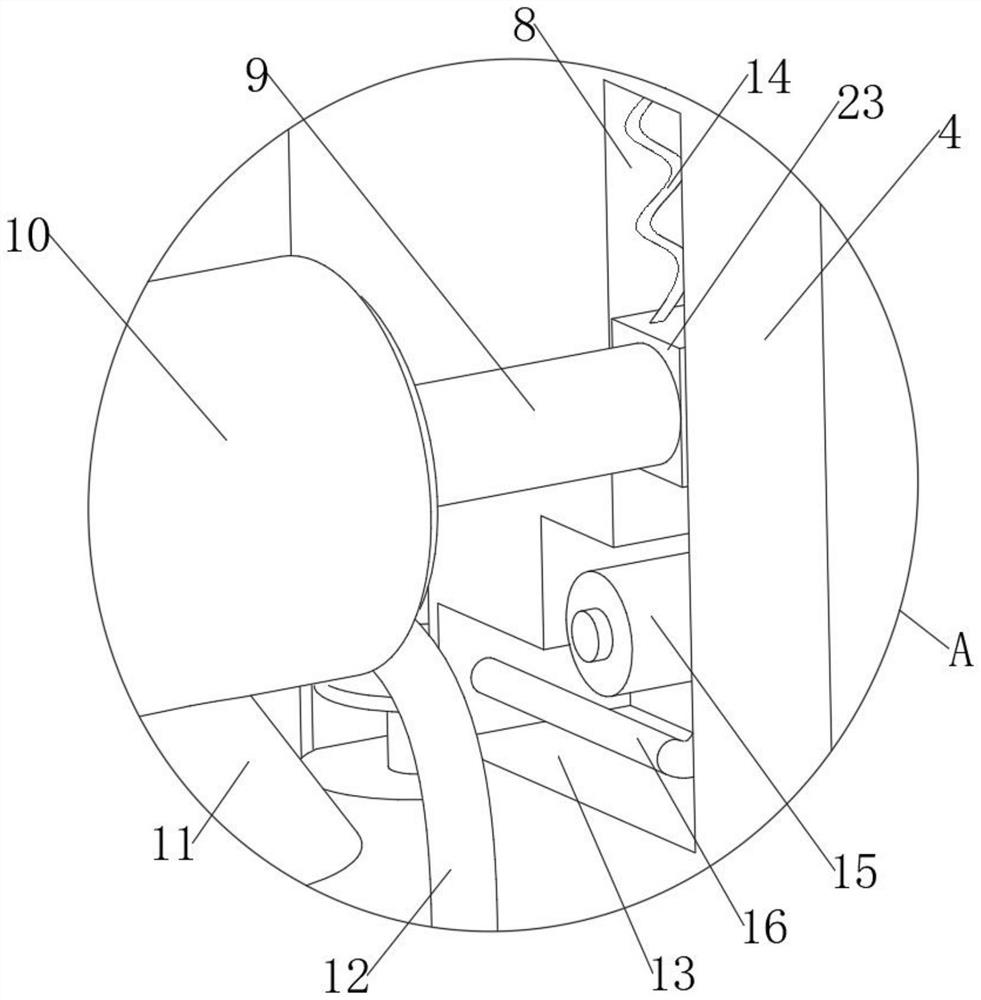
[0043] This embodiment is an improvement made on the basis of Embodiment 2. For details, please refer to Figure 1-6 , the inside of the sliding sleeve 10 is also slidably connected with a push plate 19, the push plate 19 is used to abut on the extension plate 7, the push plate 19 is connected with the rack 21, and a third spring 20 is also installed inside the sliding sleeve 10. Three springs 20 are connected to the push plate 19 , and the third spring 20 is used to push the push plate 19 to reset.
[0044] Automatic drive: according to Figure 4 As shown, when the sliding sleeve 10 slides to one end, the push plate 19 will pull the sliding sleeve 10 against the extension plate 7 , thereby causing the push plate 19 on the sliding sleeve 10 to also interfere with the extension plate 7 . Squeeze the push plate 19 and slide it to the right, according to Figure 5 As shown in the figure, the rack 21 is driven to slide by the push plate 19, so that the rack 21 in the second embo...
PUM
 Abstract
Description
Claims
Application Information
 - R&D
- Intellectual Property
- Life Sciences
- Materials
- Tech Scout
- Unparalleled Data Quality
- Higher Quality Content
- 60% Fewer Hallucinations
Browse by: Latest US Patents, China's latest patents, Technical Efficacy Thesaurus, Application Domain, Technology Topic, Popular Technical Reports.
© 2025 PatSnap. All rights reserved.Legal|Privacy policy|Modern Slavery Act Transparency Statement|Sitemap|About US| Contact US: help@patsnap.com