Electric power detection method

A technology of electric power detection and detection box, which is applied to the parts of electrical measuring instruments, measuring electricity, measuring devices, etc., can solve the problems of affecting the service life of the detection equipment in the detection box, affecting the convenience of use, and difficulty in finding the detection line. , to achieve the effect of good use effect, convenient use and avoid chaotic arrangement

Pending Publication Date: 2022-07-15
彭林辉
View PDF0 Cites 2 Cited by
  • Summary
  • Abstract
  • Description
  • Claims
  • Application Information

AI Technical Summary

Problems solved by technology

[0003] In the process of using the existing electric power detection equipment, the detection equipment is usually transported to the power equipment to be tested, by opening the detection equipment and selecting various internal detection lines, by selecting the target detection line and connecting with the detection equipment, and By operating the movable end of the detection line, the detection head on the movable end of the detection line and the equipment to be tested are used for detection. However, there are many types of detection that are actually required, and the types of detection lines are many and complex. In practice, multiple groups of detection appear after repeated use. Due to the arrangement and winding of the mixed wheels, it is difficult to find the detection line for target detection during subsequent detection, which actually greatly affects the convenience of use during detection. The detection line is troublesome to organize and the use effect is not good.
[0004] In addition, the existing power testing equipment usually needs to be sealed and stored after use to prevent the dust in the environment from falling on the interface of the testing equipment. However, the sealing cover is actually used to seal the testing box from above However, affected by the upward and downward movement of the sealing cover, when the actual sealing cover covers the top of the detection box, there is still a certain gap at the sealing place. The gas will enter the inside of the detection box, which will affect the service life of the detection equipment in the detection box

Method used


Image

  • Electric power detection method
  • Electric power detection method
  • Electric power detection method

Examples


no. 1 example

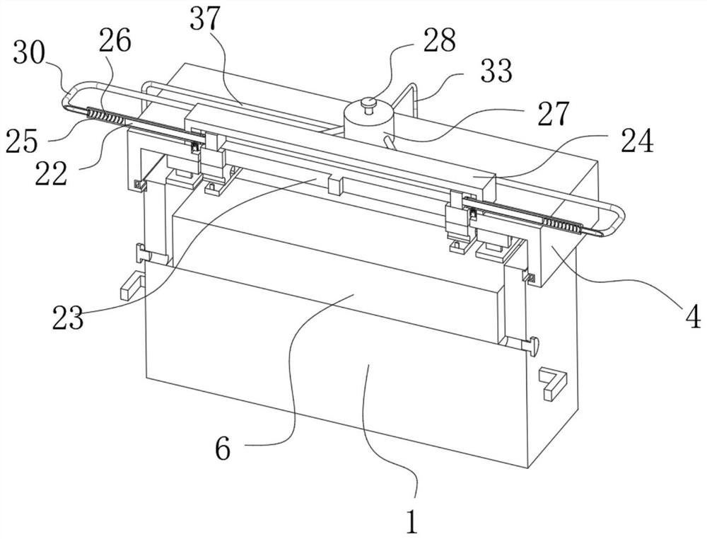
[0038] The first embodiment: as figure 1 , figure 2 , image 3 , Figure 5 , Image 6 , Figure 7 , Figure 8 and Figure 9 As shown, keep the sealing cover 4 open, and clamp the active end of the detection line into the slot 9, so that one side of the active end of the detection line is placed between the partition plates 7, and put the sleeve plate 12 on the top surface of the baffle 13. Sleeve into the No. 1 slot 10 of the partition plate 7, and then place the pressure plate 14 on the front of the movable seat 8, so that the mounting bolt 15 sleeved on the pressure plate 14 is threadedly sleeved with the threaded hole 19, and the clamping rod is 16. Clamp the detection wire end, cover the sealing cover 4 and start the air pump 32, so that the air pump 32 passes the gas into the control sleeve 27 through the No. 2 pipe 33, and makes the entering gas enter the fixed pipe 25 through the No. Inside, the gas entering the fixed pipe 25 pushes the sleeve rod 22 to move, wh...

no. 2 example

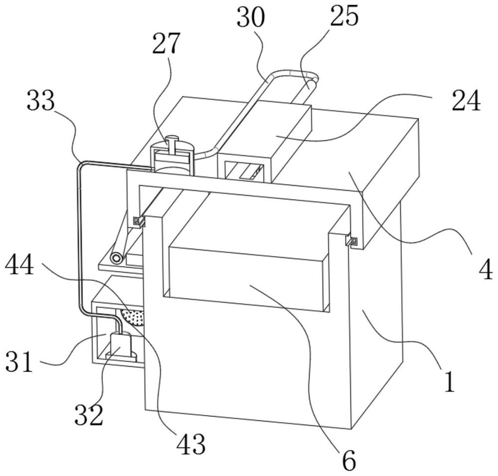
[0045] Second embodiment: as figure 1 , figure 2 , image 3 , Figure 4 and Figure 12 As shown, after the detection equipment in the equipment seat 6 inside the detection box 1 completes the detection work, the used detection line is clamped in the clamping slot 9 of the movable seat 8, the upper pressure plate 14 is installed, and the sealing cover 4 is covered, At the same time, the movable plug 41 is opened, and the air pump 32 is activated, so that the air pump 32 passes the gas into the control sleeve 27 through the No. 2 pipe 33. With the passage of the gas, the entering gas enters the fixed pipe 25 through the No. 1 pipe 30 and pushes the gas into the fixed pipe 25. The inner sleeve rod 22 moves, and after the sleeve rod 22 pushes the top plate 21 to move, the movable seat 8 moves and completes the automatic alignment, and at the same time, the front end of the sleeve rod 22 moves to the side of the air guide mechanism 39, and continues to introduce gas, The gas w...

no. 3 example

[0050] The third embodiment: as figure 1 , figure 2 , image 3 , Figure 4 , Figure 8 and Figure 11 As shown, when the sealing cover 4 is closed and the air pump 32 is started, as the gas is passed into the control sleeve 27, part of the air enters the fixed pipe 25 through the No. 1 pipe 30, and part of the air enters the fixed pipe 25 through the No. 3 pipe 37. In the elastic airbag 36, as the elastic airbag 36 is continuously inflated and collided, the elastic airbag 36 after the collision is clamped in the No. 2 ring groove 35 on the outer surface of the detection box 1, and the sealing between the detection box 1 and the sealing cover 4 is completed. At the same time, the sealing cover 4 and the detection box 1 are successfully locked, and the sealing cover 4 cannot be turned over to open. After continuous ventilation completes the purging and cooling, the adjusting rod 28 is rotated downward, so that the sealing plug 29 moves down to seal the No. 1 pipe 30 and No....


PUM


Abstract

The invention discloses an electric power detection method, and the method employs an electric power detection device, the device comprises a detection box and a sealing cover, the detection box is internally provided with an installation cavity, the inner surface of the installation cavity is fixedly provided with a device seat, and the inner surface of the sealing cover is fixedly connected with a separation plate. The sleeve rod is pushed to move, so that the top plate and the sliding plate push the movable seat to move, and the movable seat moves to pull the movable end of the detection line to move, so that the multiple groups of detection lines pull the detection line to slide along the partition plate, and automatic carding and arrangement of the multiple groups of detection lines are realized; in the next use process, the sealing cover is opened, and the sorted detection line is directly selected from the inner surface of the sealing cover, so that disordered arrangement of detection is effectively avoided, the target detection line is conveniently selected, the convenience in actual power detection is improved, the efficiency of emergency power detection is improved, power failure reasons are diagnosed in advance, and the use effect is good.

Description

technical field [0001] The invention relates to the technical field of power detection equipment, in particular to a power detection method. Background technique [0002] In the process of ensuring power production and power grid operation, power testing equipment is usually used to test, verify, detect and accept it, which provides a reliable guarantee for the safety and reliability of power operation. [0003] In the existing power detection equipment, during use, the detection equipment is usually transported to the power equipment to be tested, by opening the detection equipment and selecting a variety of internal detection lines, by selecting the target detection line to connect with the detection equipment, and By operating the movable end of the detection line, the detection head on the movable end of the detection line and the equipment to be tested are used for detection. However, there are many types of detection actually required, and the types of detection lines ...

Claims


Application Information

Patent Timeline
Patent Type & Authority Applications(China)
IPC IPC(8): G01R31/00G01R31/08G01R1/02G01R1/04B25B11/00
CPCG01R31/00G01R31/08G01R1/04G01R1/02B25B11/00
Inventor 彭林辉
Owner 彭林辉
Why Eureka
Try Eureka