
Three-phase reactor on-load switch clamping potential structure and reactor

A technology of three-phase reactors and reactors, which is applied in the field of reactors, can solve problems such as neutral point breakdown damage switches, and achieve the effect of protecting switches and preventing discharge breakdown

Pending Publication Date:
View PDF0 Cites 0 Cited by
  • Summary
  • Abstract
  • Description
  • Claims
  • Application Information

AI Technical Summary

Problems solved by technology

Due to the different installation positions of the three-phase neutral point bushing, the lengths of the three-phase leads connected from the switch to the neutral point bushing are different, and there is also a certain potential difference in the test line connected to the neutral point bushing , There will be a large potential difference between the neutral point test phase and the non-test phase on the load switch. If the potential difference is too large, it will cause breakdown between the neutral points and eventually damage the switch.

Method used


Image

  • Three-phase reactor on-load switch clamping potential structure and reactor
  • Three-phase reactor on-load switch clamping potential structure and reactor

Examples


Embodiment 1

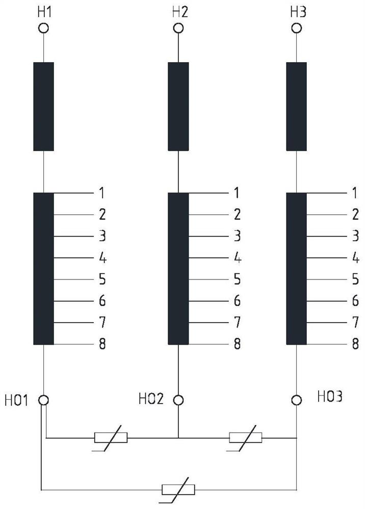
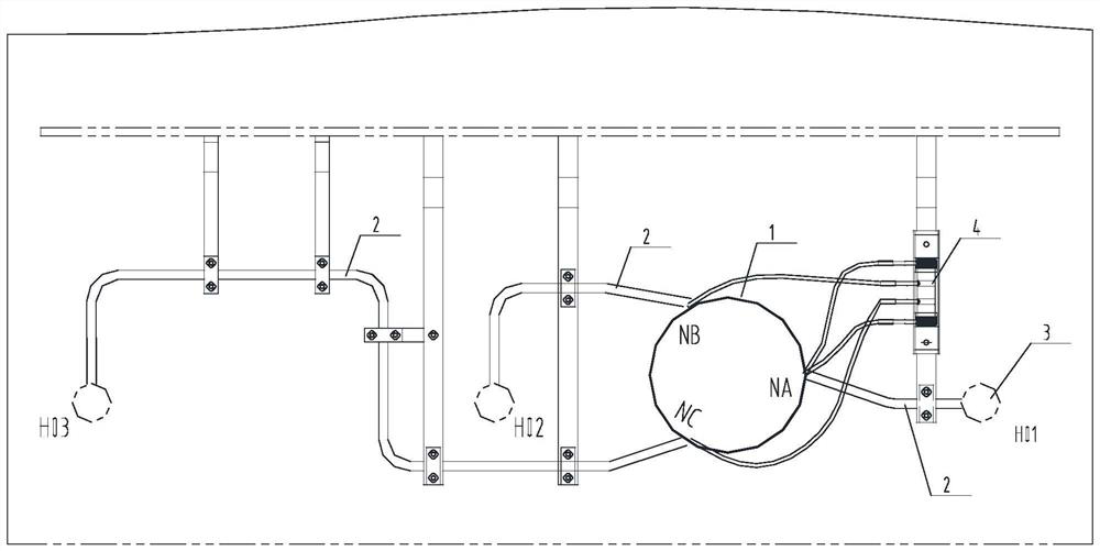
[0022] The invention discloses a structure for clamping potential of a three-phase reactor on-load switch, specifically as follows: figure 1 and figure 2 As shown, the structure includes:

[0023] A potential clamping component is added between the three neutral points of the on-load switch 1 of the reactor.

[0024] In some embodiments, the potential clamping component adopts a ZnO valve plate 4 .

[0025] In some embodiments, the number of the ZnO valve plates 4 is set according to the set on-voltage.

[0026] In some embodiments, the ZnO valve plates 4 are equally divided into three groups, and two ends of each group are respectively connected in parallel with the three-phase neutral point terminals of the on-load switch 4 .

[0027] In some embodiments, the ZnO valve plates 4 are evenly divided into three groups, one group of ZnO valve plates 4 for each phase in the three-phase neutral point, and four terminals are drawn out, and one group is connected between the neut...


PUM


Abstract

The invention provides a potential clamping structure of an on-load switch of a three-phase reactor and the reactor, and the structure is characterized in that ZnO valve plates are additionally arranged among three neutral points of the on-load switch of the reactor for potential clamping, and the three neutral points of the on-load switch are connected with a neutral point sleeve through lead cables; the ZnO valve plates are averagely divided into three groups, each phase of the three-phase neutral points is a group of ZnO valve plates, four terminals are led out, and one group of ZnO valve plates is connected between every two phases of neutral points; and if the potential difference between the neutral points of two adjacent phases of the on-load switch of the reactor is lower than the potential at the two ends of the ZnO valve plate, the ZnO valve plate is not conducted, the neutral points of the two adjacent phases are in an insulated state, and if the ZnO valve plate is conducted, the inter-phase potential of the neutral points of the on-load switch is clamped. According to the scheme provided by the invention, when the inter-phase potential difference exceeds the clamping potential of the ZnO valve plate, the line where the ZnO valve plate is located is instantly conducted, so that discharge breakdown between neutral points on the on-load switch is prevented, and the switch is effectively protected.

Description

technical field [0001] The invention belongs to the technical field of reactors, and in particular relates to a structure and a reactor for a three-phase reactor on-load switch to clamp potential. Background technique [0002] The three-phase shunt reactor is equipped with an on-load switch, which can adjust the compensation capacity of the shunt reactor within a certain range. Compared with the common fixed-capacity high-voltage shunt reactor, it can meet the higher requirements of power users on the transmission quality. The high voltage side of the reactor is directly connected to the transmission line, the neutral point side is connected to the three neutral point bushings through the neutral point of the on-load switch, and the external connection is grounded. In order to meet the test requirements for single-phase reactance measurement of three-phase shunt reactors, the three neutral points on the switch need to be independent of each other. Due to the different insta...

Claims


Application Information

Patent Timeline
Patent Type & Authority Applications(China)
IPC IPC(8): H01F27/40
CPCH01F27/40
Inventor 张静程从明王永强王二涛孙旭杨新刘学涛
Learn More