Inductor winding mechanism and automatic inductor winding equipment

A winding mechanism and inductor technology, which is applied in the manufacture of inductors/transformers/magnets, circuits, electrical components, etc., can solve problems such as low work efficiency, achieve high work efficiency, improve the degree of automation, and ensure the effect of winding quality

Active Publication Date: 2022-07-15
淮安市文盛电子有限公司
View PDF8 Cites 0 Cited by
  • Summary
  • Abstract
  • Description
  • Claims
  • Application Information

AI Technical Summary

Problems solved by technology

[0004] The purpose of this invention is to provide an inductance winding mechanism to solve the problem of

Method used


Image

  • Inductor winding mechanism and automatic inductor winding equipment
  • Inductor winding mechanism and automatic inductor winding equipment
  • Inductor winding mechanism and automatic inductor winding equipment

Examples


Example Embodiment

[0039] Example 1

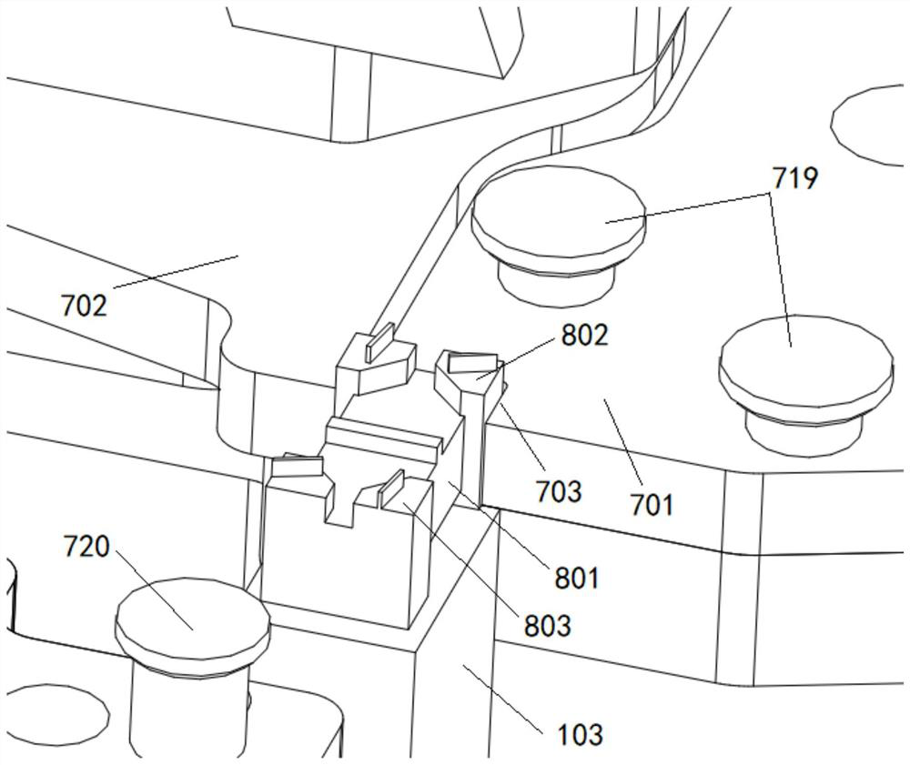
[0040] This embodiment provides an inductor winding mechanism, such as image 3 As shown, the inductor 800 includes a magnetic core 801. The two ends of the magnetic core 801 are respectively provided with a first solder pin 802 and a second solder pin 803. The first solder pin 802 and the second solder pin 803 are provided with wires for positioning the wires. Slot, the wire is passed through the slot and then wound on the magnetic core. The inductor winding mechanism mainly includes a clamp, a wire crimping seat, a crimping thimble and a needle nozzle.

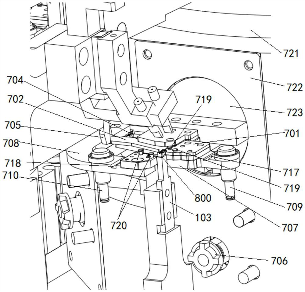
[0041] Please refer to figure 2 and image 3, the clamp is rotatably mounted on the conveying mechanism 700, and the conveying mechanism 700 in this embodiment is described by taking the indexing turntable as an example. The fixture includes a fixed clamping plate 701 and a movable clamping plate 702 that cooperate with each other. The fixed clamping plate 701 is provided with a workpiece slot 703 , a...

Example Embodiment

[0057] Example 2

[0058] In this embodiment, two wires are wound on the magnetic core 801 of the inductor 800 at the same time. The difference between this embodiment and Embodiment 1 is that the first column 719 and the second column 720 are respectively installed on the fixed splint 701 and the second wire pressing seat 708. There is a limit protrusion on the top of the . The wire is pressed by the wire thimble 1 709 and then tensioned on the column 1 719, and then passes through the first welding leg 802; the wire after winding is passed through the second welding leg 803 and then tensioned on the column 2 720, and then by the second welding leg 803. Press the thimble II 710 to press down.

[0059] Please refer to Figure 4 to Figure 6 , in order to realize automatic wire supply, this embodiment also includes two needle nozzles 203 installed in parallel on the fixed sleeve 204 to guide the movement of the wire. After passing through the needle nozzle 203, it should be ...

Example Embodiment

[0065] Example 3

[0066] This embodiment provides an inductance automatic winding device including the winding mechanism described in Embodiment 1 or Embodiment 2.

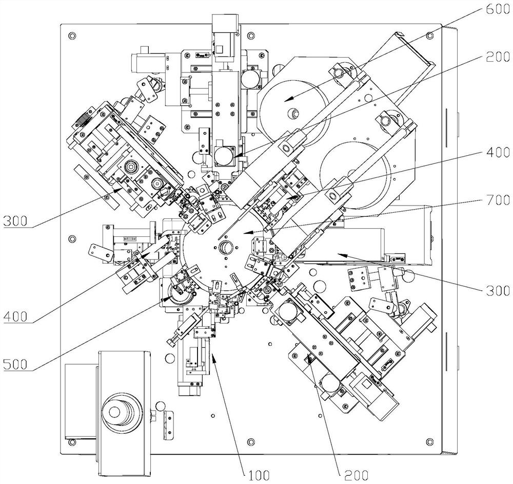
[0067] like figure 1 As shown, the conveying mechanism 700 is an indexing turntable 722. Multiple sets of clamps and wire crimping seats are installed on the indexing turntable 722 at equal intervals. The conveying mechanism 700 sequentially sends each group of clamps and wire crimping bases to the feeding station 100, the wire winding Station 200 , welding station 300 , waste discharge station 400 and blanking station 500 . When two layers of wires need to be wound, two rounds of the above-mentioned stations can be repeatedly set on the periphery of the indexing turntable 722, so that two layers of wires are repeatedly wound.

[0068]Among them, the push rod 705 is located on the feeding station 100 and the unloading station 500, the support block 103 and the cylinder 5 are located on the feeding station 100, ...


PUM


Abstract

The inductor winding mechanism comprises a clamp, the clamp comprises a fixed clamping plate and a movable clamping plate which are matched with each other, and the movable clamping plate rotates towards one side of the fixed clamping plate so as to clamp one end of an inductor and enable the other end of the inductor to be suspended; the fixed clamping plate and the movable clamping plate are driven by a driving device to rotate and retreat simultaneously, so that the wire is wound on a suspended magnetic core of the inductor; a wire pressing thimble is mounted on the wire pressing seat in an up-down sliding manner; the wire pressing ejector pin presses the wire; the wire pressing seat is provided with a pressing groove which is located between the wire pressing ejector pin and the inductor. When the wire is welded on the two welding feet of the inductor, the tensioned wire is pressed into the pressing groove by the liftable pressing claw and is broken. Automatic winding can be achieved, wire ends are automatically cut off after winding is completed, and the operation efficiency is high.

Description

technical field [0001] The invention belongs to the technical field of inductance manufacturing, and in particular relates to an inductance automatic winding device. Background technique [0002] SMD inductors need to wind the wire on the magnetic core. When winding, the inductor needs to be clamped reliably, and then the inductor is rotated, and the wire is wound on the magnetic core. An existing automatic winding equipment fixture is described in CN212209214U, including: a fixed plate, which is immovably fixed on the fixture mounting plate, and a movable plate, which is L-shaped, and the corner position of the L line is rotatably fixed on the fixture installation. On the plate, one side of the L-shape is matched with the fixed plate, and one end of the matched side forms a jaw for clamping the magnetic core with the fixed plate. Against the clamp spring, the other end of the clamp spring abuts against the clamp mounting plate, and the clamp spring is always in a compresse...

Claims


Application Information

Patent Timeline
IPC IPC(8): H01F41/094
CPCH01F41/094
Inventor 李骥李志盼孙敏杨俊
Owner 淮安市文盛电子有限公司
Why Eureka
Try Eureka