Moving magnetic suspension type multi-wheel transmission device

A multi-wheel drive and magnetic levitation technology, applied in electromechanical devices, electric components, permanent magnet clutches/brakes, etc., can solve the problems of large wear, reduction and low power generation efficiency of contact transmission

Pending Publication Date: 2022-07-15
刘开年
View PDF0 Cites 0 Cited by
  • Summary
  • Abstract
  • Description
  • Claims
  • Application Information

AI Technical Summary

Problems solved by technology

[0008] The transmission mode between the existing mechanical structures is generally a contact transmission connection, and the contact transmission wears a lot. If the transmission is used for power generation, the generated power will be reduced due to friction loss, and the power generation efficiency is not high.

Method used


Image

  • Moving magnetic suspension type multi-wheel transmission device
  • Moving magnetic suspension type multi-wheel transmission device
  • Moving magnetic suspension type multi-wheel transmission device

Examples


Embodiment 1

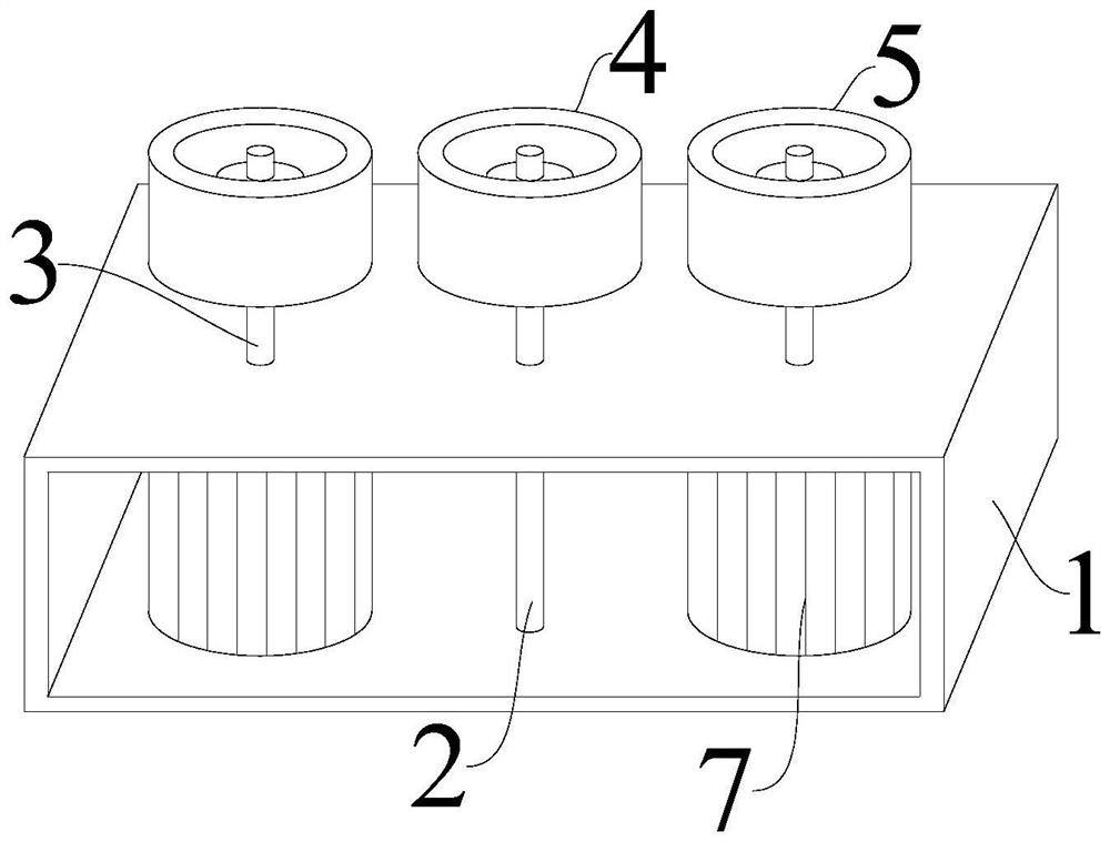
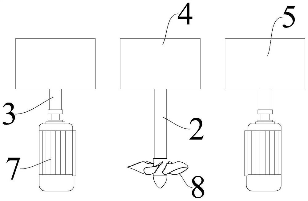
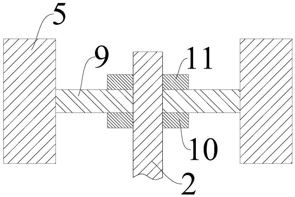
[0038] Please refer to Figure 1-Figure 3 , figure 1Shown is a schematic structural diagram of the induced magnetic suspension type multi-wheel transmission provided in Embodiment 1 of the present invention; figure 2 Shown is the front view of the induced magnetic suspension type multi-wheel transmission provided by Embodiment 1 of the present invention; image 3 Shown is a partial cross-sectional view of the position of the driving magnetic wheel 4 provided in Embodiment 1 of the present invention.

[0039] This embodiment provides a driving magnetic levitation type multi-wheel transmission device, which includes an installation frame 1, the installation frame 1 is rotatably provided with a drive shaft 2 and a driven shaft 3, and the drive shaft 2 is detachably provided with a drive magnetic wheel 4. The driven shaft 3 is detachably provided with a driven magnetic wheel 5 . The driving magnetic wheel 4 is spaced from the driven magnetic wheel 5 .

[0040] The above-mentio...

Embodiment 2

[0047] Please refer to Figure 4 , Figure 4 Shown is a schematic structural diagram of the induced magnetic suspension type multi-wheel transmission provided in Embodiment 2 of the present invention.

[0048] The difference between this embodiment and Embodiment 1 is that when the driven magnetic suspension multi-wheel transmission device needs to be used for transmission, the mounting frame 1 is provided with a driving motor 6 , and the driving shaft 2 is provided on the transmission shaft of the driving motor 6 .

[0049] At this time, the above-mentioned driving shaft 2 is driven to rotate by the driving motor 6, and the driving shaft 2 drives the driving magnetic wheel 4 to rotate; because the magnetic pole of the outer side wall of the above-mentioned driving magnetic wheel 4 is the same as the magnetic pole of the outer side wall of the above-mentioned driven magnetic wheel 5, the rotating The driving magnetic wheel 4 drives the driven magnetic wheel 5 to rotate, and t...


PUM


Abstract

The invention provides an actuating magnetic suspension type multi-wheel transmission device, and relates to the technical field of transmission devices. A priming magnetic suspension type multi-wheel transmission device comprises a mounting frame, the mounting frame is rotationally provided with a driving shaft and a driven shaft, the driving shaft is detachably provided with a driving magnetic wheel, the driven shaft is detachably provided with a driven magnetic wheel, and the driving magnetic wheel and the driven magnetic wheel are arranged at intervals. And the magnetic pole of the outer side wall of the driving magnetic wheel is the same as that of the outer side wall of the driven magnetic wheel. According to the invention, non-contact transmission can be realized, the transmission efficiency is high, the loss is small, and the power generation efficiency is improved.

Description

technical field [0001] The invention relates to the technical field of transmission devices, in particular to a driven magnetic suspension type multi-wheel transmission device. Background technique [0002] In electromagnetism, when two magnets or magnets attract or repel each other, or when a current-carrying wire generates a magnetic field around it, causing the needle to deflect, or when the closed circuit moves in a non-uniform magnetic field, a current will appear in the closed circuit , which are all phenomena related to magnetism. All phenomena related to magnetism are also related to magnetic fields. [0003] There are many types of magnets, which are generally divided into two categories: hard (permanent) magnets (magnetic retention for a long or permanent period) and soft magnets (magnetic for a short period of time). The magnets we call generally refer to permanent magnets. . Permanent magnets are divided into two categories: [0004] The first category is: me...

Claims


Application Information

Patent Timeline
IPC IPC(8): H02K49/10H02K7/18
CPCH02K49/102H02K7/1823H02K7/183
Inventor 刘开年
Owner 刘开年
Why Eureka
Try Eureka