
Sensor device

A sensor device and sensing element technology, applied in the field of signal sensing, can solve problems such as easy deformation of sealing rings, failure of fluid leakage, etc.

Pending Publication Date: 2022-07-19
HANGZHOU SANHUA RES INST CO LTD
View PDF0 Cites 0 Cited by
  • Summary
  • Abstract
  • Description
  • Claims
  • Application Information

AI Technical Summary

Problems solved by technology

However, in practice, especially for high-temperature and high-pressure fluids, the sealing ring is prone to deformation and failure, and the fluid in the flow channel may leak into the inner cavity

Method used


Image

  • Sensor device
  • Sensor device
  • Sensor device

Examples


Embodiment Construction

[0026] The exemplary embodiments of the present application will be described in detail below with reference to the accompanying drawings. If several specific embodiments exist, the features of these embodiments may be combined with each other without conflict. When the description refers to the drawings, the same numbers in different drawings refer to the same or similar elements unless otherwise indicated. What is described in the following exemplary embodiments does not represent all embodiments consistent with the present application; rather, they are only consistent with some aspects of the present application as recited in the claims of the present application Examples of devices, products and / or methods.

[0027] The terms used in this application are only for the purpose of describing specific embodiments, and are not intended to limit the protection scope of this application. As used in the specification and claims of this application, the singular forms "a," "the,"...


PUM


Abstract

The invention provides a sensor device. The sensor device comprises a shell and a sensing assembly, the sensing assembly comprises a circuit substrate, at least one sensing element and a sleeve; the sensor device is also provided with an inner cavity and a channel; the inner cavity and the channel are respectively positioned on different sides of the circuit substrate in the thickness direction; the sleeve is provided with a sleeve wall; the tail end, in the axial direction of the channel, of the cylinder wall is connected with the circuit substrate in a sealed mode. The sleeve wall of the sleeve is located on the periphery of the channel. The shell is provided with a matching part, and the matching part is provided with an accommodating part; the sleeve is at least partially accommodated in the accommodating part; the matching part comprises a first peripheral wall part forming the accommodating part; the first peripheral wall part is connected with the peripheral side of the sleeve wall of the sleeve in a sealing manner; and the inner cavity is not communicated with the channel. According to the sensor device provided by the invention, the sealing performance between the inner cavity and the flow channel is relatively good.

Description

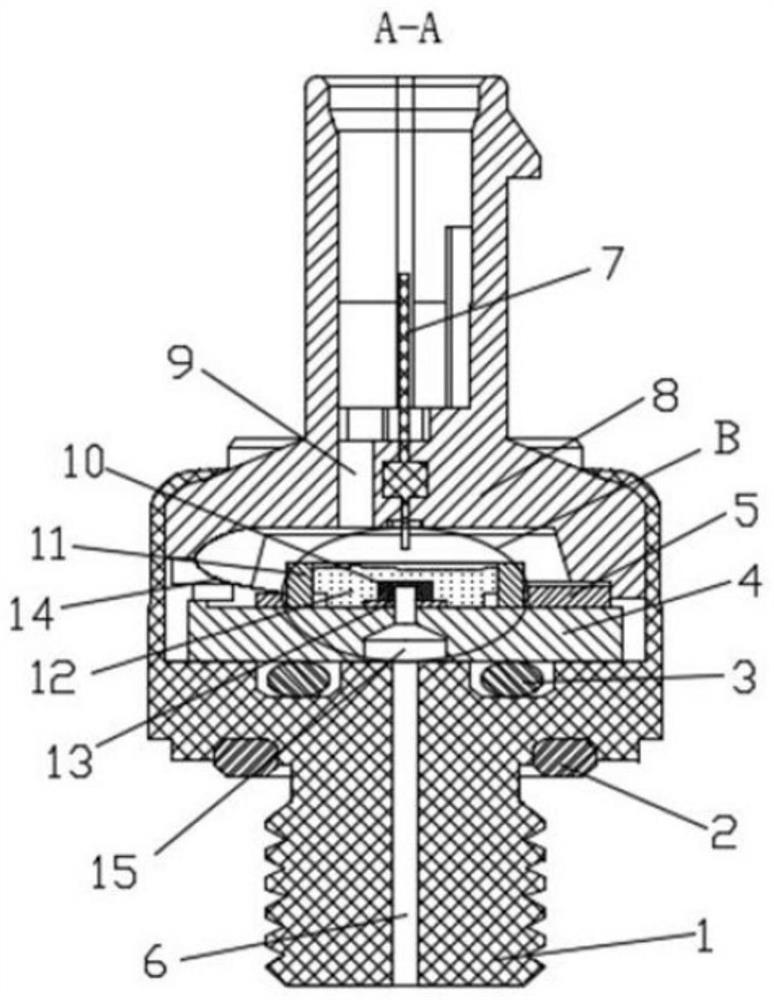
technical field [0001] The present application relates to the technical field of signal sensing, in particular to a sensor device. Background technique [0002] Sensors in related technologies, such as figure 1 As mentioned above, it includes a bottom shell 1, an upper shell 8, a ceramic base 4, and a through hole 15 is formed in the ceramic base 4. The surface of the ceramic base 4 is bonded with a back pressure chip 10 through an adhesive 13. The flow channel 6 is used for The drainage fluid reaches the through hole 15 and then reaches the back pressure cavity of the back pressure chip 10 . The bottom case 1 has a groove with a sealing ring 3 in the groove. The sealing ring 3 seals the ceramic base 4 to prevent the fluid from the lower part from leaking into the inner cavity of the upper part of the ceramic base 4 . However, in practice, especially for high-temperature and high-pressure fluids, the sealing ring is prone to deformation and failure, and the fluid in the fl...

Claims


Application Information

Patent Timeline
IPC IPC(8): G01L9/06G01L19/00G01K7/22G01K13/02G01K1/08G01K1/10G01K1/14
CPCG01L9/06G01L19/00G01K7/22G01K13/02G01K1/08G01K1/10G01K1/14G01L19/14G01K1/18G01K1/16H05K5/0209H05K5/066H05K5/069
Inventor 万霞饶欢欢王新建逯新凯金骑宏黄隆重黄宁杰
Owner HANGZHOU SANHUA RES INST CO LTD
Learn More