
Hospital clinical laboratory test tube batch taking equipment

A laboratory and batch technology, applied in the field of medical devices, can solve the problems of test tube loosening and falling off, low work efficiency, test tube fragmentation, etc., and achieve the effect of improving the use effect, improving safety, and firm clamping

Pending Publication Date: 2022-07-22
王云鹏
View PDF1 Cites 0 Cited by
  • Summary
  • Abstract
  • Description
  • Claims
  • Application Information

AI Technical Summary

Problems solved by technology

[0004] There are certain disadvantages in the use of the above-mentioned device. When the traditional equipment is used for batch test tube picking operations, it cannot simultaneously fix multiple rows of test tubes. The traditional equipment adopts a single-row fixed structure, so that it can only be used once. The work efficiency is low when picking and transferring single-row test tubes; secondly, the traditional equipment does not have a limit auxiliary structure, and different types of test tubes have different calibers. It is too large to cause the test tubes to be fragmented and cannot be used for test tubes of different calibers; secondly, the traditional equipment does not have an auxiliary fixing structure. When the traditional equipment is used to fix the test tubes, because the whole row of test tubes is relatively long, it is easy to fix the middle test tubes when fixing the test tubes. The phenomenon of loosening and falling off occurs, and the safety is poor, which brings certain adverse effects to users

Method used


Image

  • Hospital clinical laboratory test tube batch taking equipment
  • Hospital clinical laboratory test tube batch taking equipment
  • Hospital clinical laboratory test tube batch taking equipment

Examples


Embodiment Construction

[0030] In order to further illustrate the technical means and effects adopted by the present invention to achieve the predetermined purpose of the invention, the specific embodiments, structures, features and effects of the present invention are described in detail below in conjunction with the accompanying drawings and preferred embodiments.

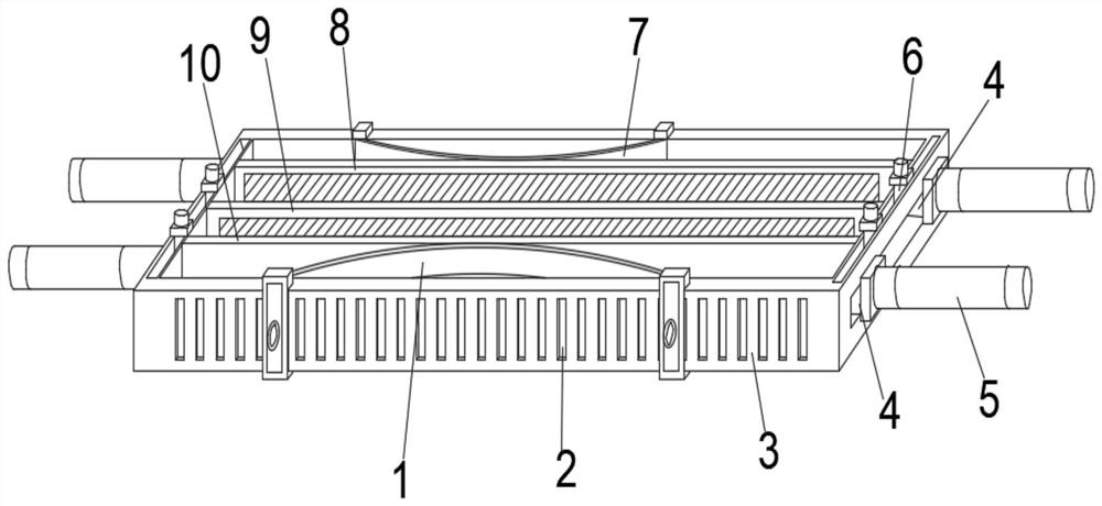
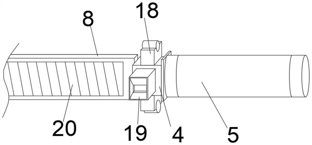
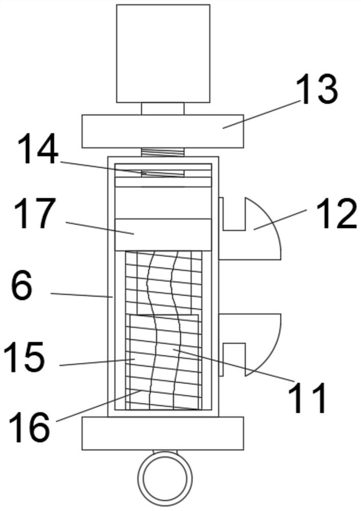
[0031] like Figure 1-5 As shown in the figure, a device for taking test tubes in batches in a hospital laboratory department includes a fixed frame 3 and a fixed middle plate 9. The fixed middle plate 9 is fixedly installed at the inner middle position of the fixed frame 3, and the inner side of the fixed frame 3 is close to the fixed middle plate 9. One side of the fixed frame 3 is movably installed with the first splint 8 for gripping the test tube, the inner side of the fixed frame 3 is movably installed with the second splint 10 for gripping the test tube, and the inner side of the fixed middle plate 9 is movable A first support pl...


PUM


Abstract

The hospital clinical laboratory test tube batch taking equipment comprises a fixing frame and a fixing middle plate, the fixing middle plate is fixedly installed in the middle of the inner side of the fixing frame, and a first clamping plate used for clamping test tubes is movably installed on the side, close to the fixing middle plate, of the inner side of the fixing frame; a second clamping plate for clamping a test tube is movably installed on the other side, close to the fixed middle plate, of the inner side of the fixed frame, and a first supporting plate and a second supporting plate which are used in cooperation with the first clamping plate and the second clamping plate are movably installed on the inner side of the fixed middle plate; limiting clamping bases used for limiting the moving range of the first clamping plate and the second clamping plate are movably installed at the two ends of the fixing frame. By means of the arrangement of the first clamping plate and the second clamping plate, the batch taking device for the test tubes in the clinical laboratory of the hospital is provided with a double-row fixing structure, the fixing operation of the double-row test tubes can be completed at a time, and use is convenient.

Description

technical field [0001] The invention belongs to the technical field of medical devices, and more particularly relates to a batch-taking device for test tubes in a hospital laboratory department. Background technique [0002] A device for taking test tubes in batches in a hospital laboratory department is a device used in a hospital laboratory department to take test tubes in batches in a hospital laboratory department. The device can be used to take multiple test tubes at one time. , improve its work efficiency. [0003] The patent document of the patent number CN209735653U discloses a batch test tube transfer rack in the process of blood mixing and preservation, including a mixer, a constant temperature box and a transfer rack. The transfer rack is provided with a number of test tube holes in an array, and the test tube holes are provided with anti-dropping The rubber ring, the two ends of the transfer frame are respectively provided with fixed slots, the fixed slots are p...

Claims


Application Information

Patent Timeline
IPC IPC(8): B01L9/06
CPCB01L9/06
Inventor 王云鹏
Owner 王云鹏
Learn More