Mechanical arm cutting guide rail for manufacturing industrial automatic control device

A technology of automatic control device and mechanical arm, which is applied in the direction of manufacturing tools, sawing machine devices, sawing machine accessories, etc. It can solve the problems of material misalignment, inconvenient operation, and sudden drop in stress intensity, so as to achieve high efficiency and improve production safety. sexual effect

Active Publication Date: 2022-07-22
江苏舒扬智能装备有限公司
View PDF10 Cites 2 Cited by
  • Summary
  • Abstract
  • Description
  • Claims
  • Application Information

AI Technical Summary

Problems solved by technology

[0002]In the process of machining, in order to make the machine achieve a certain structural strength and aesthetic effect, it is often necessary to use various tubular profiles such as square tubes and round tubes. In order to make these profiles meet the needs in terms of size, they need to be cut properly. In the process of cutting materials with general devices, the stress intensity of the cutting point of the material will drop suddenly at the moment of cutting. , and in order to prevent the cutting tool from contacting the rest of the device, the cutting piece generally needs to be suspended in midair, which causes the material suspended in midair to be misaligned due to factors such as gravity. After a single cutting work It also needs to readjust the clamping state, which leads to the problem of inconvenient operation

Method used


Image

  • Mechanical arm cutting guide rail for manufacturing industrial automatic control device
  • Mechanical arm cutting guide rail for manufacturing industrial automatic control device
  • Mechanical arm cutting guide rail for manufacturing industrial automatic control device

Examples


Embodiment 1

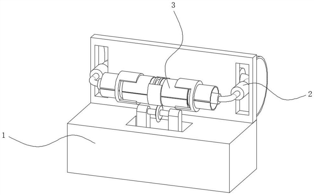
[0029] see Figure 1-Figure 5 , the present invention provides a technical solution: a mechanical arm cutting guide rail for manufacturing an industrial automatic control device, comprising a cutting box 1, a vertical frame plate is fixedly connected to the back of the upper surface of the cutting box 1, and the back of the upper surface of the cutting box 1 passes through A supporting device 2 is fixedly connected to the vertical frame plate, and a fixing device 3 is arranged in the middle of the supporting device 2 .

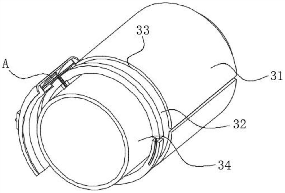
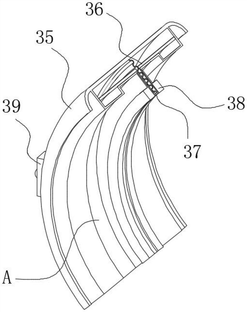
[0030] The fixing device 3 includes a half-split rotating drum 31 , the inner cavity of the half-split rotating drum 31 is fixedly connected with an inner clamping plate 32 , the left and right sides of the half-split rotating drum 31 are symmetrically provided with annular grooves 33 , and the outer surface of the half-split rotating drum 31 is provided with an annular groove 33 . Sliding outer plates 35 are symmetrically arranged on the front and rear sides ...

Embodiment 2

[0041] see Figure 1-Figure 7 , the present invention provides a technical solution: on the basis of the first embodiment, a robotic arm cutting guide rail for manufacturing an industrial automatic control device includes a cutting box 1, and a vertical frame plate is fixedly connected to the back of the upper surface of the cutting box 1, A support device 2 is fixedly connected to the back of the upper surface of the cutting box 1 through a vertical frame plate, and a fixing device 3 is arranged in the middle of the support device 2 .

[0042]The fixing device 3 includes a half-split rotating drum 31 , the inner cavity of the half-split rotating drum 31 is fixedly connected with an inner clamping plate 32 , the left and right sides of the half-split rotating drum 31 are symmetrically provided with annular grooves 33 , and the outer surface of the half-split rotating drum 31 is provided with an annular groove 33 . Sliding outer plates 35 are symmetrically arranged on the front...


PUM


Abstract

The invention belongs to the technical field of machine tool machining, and particularly relates to a mechanical arm cutting guide rail for manufacturing an industrial automatic control device. The mechanical arm cutting guide rail comprises a cutting box, a vertical frame plate is fixedly connected to the back of the upper surface of the cutting box, and a supporting device is fixedly connected to the back of the upper surface of the cutting box through the vertical frame plate; a fixing device is arranged in the middle of the supporting device and comprises a half-section rotating cylinder, and an inner clamping plate is fixedly connected to an inner cavity of the half-section rotating cylinder. According to the device, after a cutting pipe needing to be machined is installed, the degree of freedom of the cutting pipe in the middle is completely limited through the half-section rotating drum and the side clamping discs on the left side and the right side, so that the cutting pipe is not prone to shaking in the cutting process, and the cutting pipe cannot be dislocated or deviated at the moment when the cutting pipe is cut off; the axes of the segmented pipe bodies are located on the same axis all the time, so that the clamping state does not need to be adjusted again after single-time cutting work is conducted, and the continuous working process is more convenient and higher in efficiency.

Description

technical field [0001] The invention belongs to the technical field of machine tool processing, in particular to a mechanical arm cutting guide rail for manufacturing an industrial automatic control device. Background technique [0002] In the process of machining, in order to make the machine achieve a certain structural strength and aesthetic effect, it is often necessary to use various tubular profiles such as square tubes and round tubes. In order to make these profiles meet the needs in size, it is necessary to It performs appropriate cutting, and in the process of cutting the material in a general device, the cutting point of the material will drop sharply at the moment of cutting, and in order to prevent the cutting tool from contacting the rest of the device, the cutting piece is generally The suspension needs to be suspended in mid-air, which causes the material suspended in mid-air to be misaligned due to factors such as gravity, and the clamping state needs to be ...

Claims


Application Information

Patent Timeline
Patent Type & Authority Applications(China)
IPC IPC(8): B23D45/00B23D45/12B23D59/00
CPCB23D45/003B23D45/12B23D59/00
Inventor 李雷雷
Owner 江苏舒扬智能装备有限公司
Why Eureka
Try Eureka