Welding fixture for capacitor shell machining
A technology for welding fixtures and capacitors, applied in welding equipment, manufacturing tools, metal processing equipment, etc., can solve the problems of easy shaking, difficult stable clamping, and uneven clamping force of the shell, so as to achieve constant clamping force , Reduce the clamping force, reduce the effect of processing time
- Summary
- Abstract
- Description
- Claims
- Application Information
AI Technical Summary
Problems solved by technology
Method used
Image


Examples
Embodiment 1
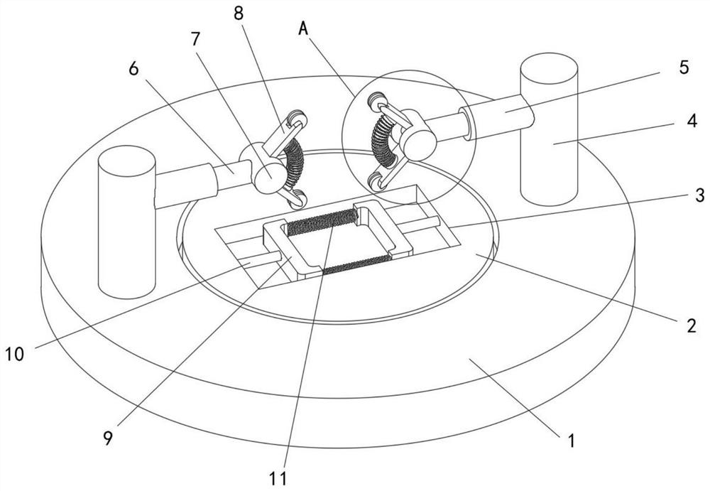
[0029] refer to Figure 1-5 , a welding fixture for capacitor shell processing, comprising a base 1, a processing seat 2 is opened inside the base 1, a processing groove 3 is opened inside the processing seat 2, and a bottom pre-clamping mechanism is arranged inside the processing groove 3, and the base 1 is provided with a bottom pre-clamping mechanism. The top and both sides of the processing base 2 are fixedly connected with support columns 4, and the side walls of the support columns 4 are symmetrically provided with top pre-clamping mechanisms;
[0030] The bottom pre-clamping mechanism includes a movable rod 10 symmetrically slidingly installed on the inner walls of both sides of the processing groove 3. The movable rod 10 is located on the inner side of the processing groove 3. The clamping arm 9 is fixedly installed at one end, and the two side walls of the adjacent clamping arms 9 are pressed. The clamping spring 11 is fixedly connected. At the beginning of the proces...
Embodiment 2
[0032] like Figure 1-5 As shown, this embodiment is basically the same as Embodiment 1. Preferably, the top pre-clamping mechanism includes a strut 5 that is symmetrically and fixedly connected to the side of the support column 4 close to the machining groove 3, and the interior of the strut 5 is slidably installed with sliding The rod 6 and the sliding rod 6 are fixedly connected with the first permanent magnet 43 at the inner end of the strut 5, the other end of the first permanent magnet 43 is fixedly connected with the first spring 42, and the other end of the first spring 42 is fixedly connected There is a first electromagnet 41. After the bottom pre-clamping mechanism is turned on, the piezoelectric ceramic 104 records the value of the capacitor shell width of different degrees on the piezoelectric current surface. The first electromagnet 41 is turned on, and the first electromagnet 41 is turned on. The permanent magnet 43 slides toward the side wall of the capacitor ca...
Embodiment 3
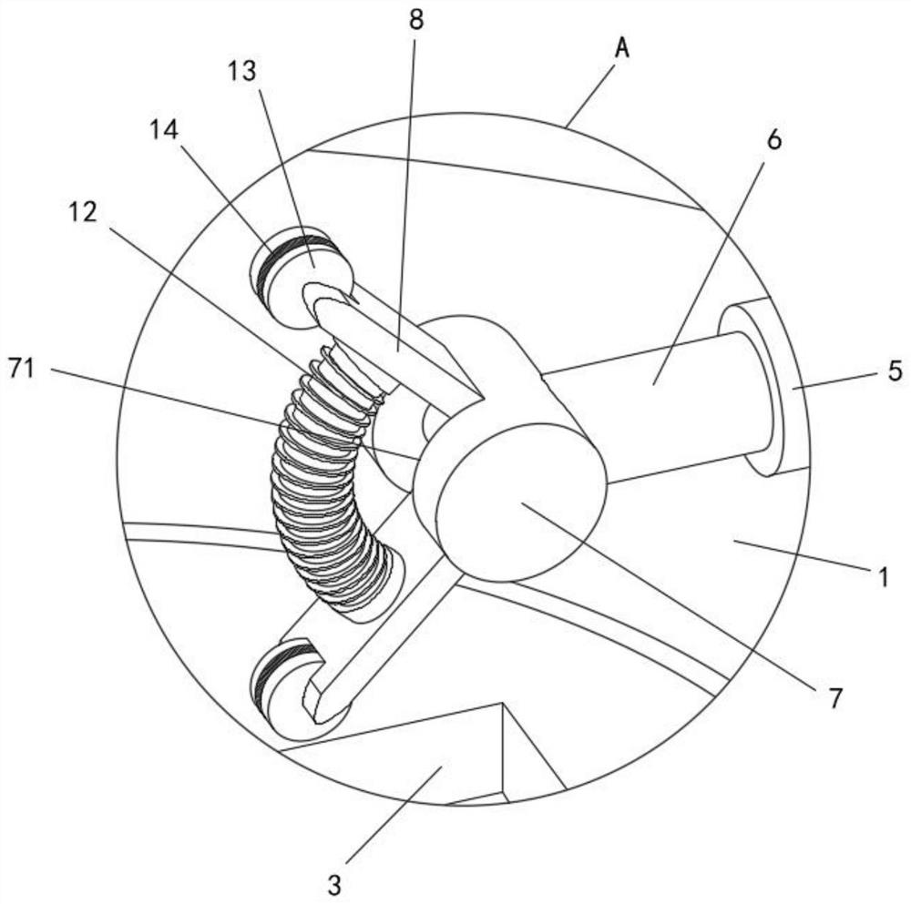
[0034] like Figure 1-5As shown, this embodiment is basically the same as Embodiment 1. Preferably, the bottom secondary clamping mechanism includes a rotating groove 71 symmetrically opened on the inner side of the rotating column 7, and two clamping plates 8 are installed symmetrically inside the rotating groove 71. The ends of each splint 8 are provided with an anti-extrusion deformation mechanism, an elastic telescopic sleeve 12 is arranged between the two splints 8 , and a second electromagnet 121 is fixedly connected to the inner center of the elastic telescopic sleeve 12 . The second springs 122 are fixedly installed on the sides, the ends of the second springs 122 are fixedly connected with the second permanent magnets 123, and the ends of the second permanent magnets 123 are fixedly installed on the side walls of the splint 8 respectively. After opening, only rough adjustment is performed on the clamping of the capacitor casing. When the clamping is finely adjusted, t...
PUM
 Abstract
Description
Claims
Application Information