
Packaging box manufacturing device and method

A technology for making a device and a packing box, which is applied in the directions of box making operation, packaging, transportation and packaging, can solve the problems of time-consuming and laborious, low installation efficiency of the buckle handle, low installation flexibility of the buckle handle, etc. The effect of flexibility

Inactive Publication Date: 2022-07-22
李欢雯
View PDF0 Cites 0 Cited by
  • Summary
  • Abstract
  • Description
  • Claims
  • Application Information

AI Technical Summary

Problems solved by technology

[0003] There are still some deficiencies in the installation of the buckle handle, and the specific shortcomings are: 1. The existing installation method of the buckle handle usually adopts a manual installation method, and the manual installation of the buckle handle is time-consuming and laborious. The installation efficiency of the handle is low, and the manual installation has the problem that the buckle handle is not installed firmly
[0004] 2. There are many shapes of existing packing boxes, and the positions of the handle openings are also different. The ordinary snap handle installation equipment can only install the snap handle for the same kind of packing box cardboard. The snap handle of this device low installation flexibility

Method used


Image

  • Packaging box manufacturing device and method
  • Packaging box manufacturing device and method
  • Packaging box manufacturing device and method

Examples


Embodiment Construction

[0030] Embodiments of the present invention are described in detail below with reference to the accompanying drawings, but the present invention can be implemented in many different ways as defined and covered by the claims.

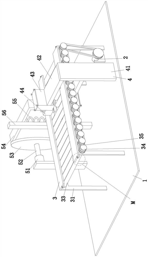
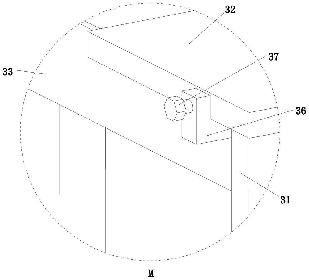
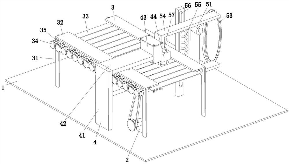
[0031] see figure 1 and Figure 4 , a packaging box making device, comprising a base plate 1, a pulley motor 2, a transport assembly 3, a handle feeding assembly 4 and a pressing assembly 5, and the pulley motor 2 is fixedly connected to the upper end surface of the base plate 1 through a motor bracket, so The upper end surface of the base plate 1 is fixedly connected with a transport assembly 3, the rear side of the transport assembly 3 is provided with a pressing assembly 5, the pressing assembly 5 is fixedly connected to the upper end face of the base plate 1, and the front side of the transport assembly 3 is provided with a handle feeding assembly 4 , the handle feeding assembly 4 is fixedly connected to the upper end face of the base plate 1 .

[...


PUM


Abstract

The invention relates to the technical field of box body manufacturing and machining, in particular to a packaging box manufacturing device and method.The packaging box manufacturing device comprises a bottom plate, a belt wheel motor, a conveying assembly, a handle feeding assembly and a pressing assembly, the upper end face of the bottom plate is fixedly connected with the belt wheel motor through a motor support, and the upper end face of the bottom plate is fixedly connected with the conveying assembly; a pressing assembly is arranged on the rear side of the conveying assembly and fixedly connected to the upper end face of the bottom plate, and a handle feeding assembly is arranged on the front side of the conveying assembly and fixedly connected to the upper end face of the bottom plate. The problems that a buckle handle is usually installed manually, time and labor are wasted, the installation efficiency is low, and installation is not firm are solved. After a packaging box paperboard is conveyed to a designated position through the conveying assembly, the handle feeding assembly is matched with the pressing assembly to press a buckle handle into a handle opening in the packaging box paperboard, the installation efficiency is improved, and the situation that the buckle handle is not firmly installed is avoided.

Description

technical field [0001] The invention relates to the technical field of box manufacturing and processing, in particular to a packaging box manufacturing device and a manufacturing method. Background technique [0002] The main function of the packaging box is to facilitate transportation, loading, unloading and storage. The material of the packaging box is generally divided into wood and corrugated cardboard. Among them, the corrugated box is the most widely used packaging box. There is a handle opening on the side, but the strength of the handle buckle is too low, so you need to install a plastic snap handle on the handle opening. [0003] There are still some deficiencies in the installation of the buckle handle. The specific shortcomings are: 1. The existing installation method of the buckle handle usually adopts the manual installation method. The manual installation of the buckle handle is time-consuming and laborious, and the buckle The installation efficiency of the h...

Claims


Application Information

Patent Timeline
Patent Type & Authority Applications(China)
IPC IPC(8): B31B50/86B31B50/04
CPCB31B50/87B31B50/04
Inventor 李欢雯
Owner 李欢雯
Learn More