
Coaxial multi-path laser transmitter and coaxial laser transmitting device for simulating countermeasure

A laser emission, multi-channel laser technology, applied in aiming devices, weapon accessories, training matching parts, etc., can solve the problems of reduced shooting accuracy, poor calibration accuracy, slow calibration speed, etc., to improve shooting accuracy, gun calibration The effect of convenience and high calibration accuracy

Pending Publication Date: 2022-07-22
张艳辉
View PDF0 Cites 0 Cited by
  • Summary
  • Abstract
  • Description
  • Claims
  • Application Information

AI Technical Summary

Problems solved by technology

The existing correction laser and shooting laser also have the following defects: 1) the correction laser that the correction laser sends is not in the same axis as the shooting laser that the shooting laser sends. The aiming point coincides; 2) When the calibration laser emitted by the calibration laser and the shooting laser emitted by the shooting laser are calibrated, a special calibrator is required, the calibration speed is slow, and the calibration accuracy is poor; 3) After the calibration laser and the shooting laser are packaged, the laser spots at different distances The size cannot be adjusted, and the laser spot size requirements for shooting training at different distances cannot be achieved. Although the distance between the calibration laser and the shooting laser is relatively close, when the shooting target is far away, the error between the two lasers will be enlarged. The lasers emitted by the correction laser and the shooting laser are difficult to converge to one point, which greatly reduces the accuracy of shooting

Method used


Image

  • Coaxial multi-path laser transmitter and coaxial laser transmitting device for simulating countermeasure
  • Coaxial multi-path laser transmitter and coaxial laser transmitting device for simulating countermeasure

Examples


Embodiment Construction

[0023] In order to make the objectives, technical solutions and advantages of the present invention clearer, the present invention will be further described in detail below with reference to the accompanying drawings and embodiments. It should be understood that the specific embodiments described herein are only used to explain the present invention, but not to limit the present invention.

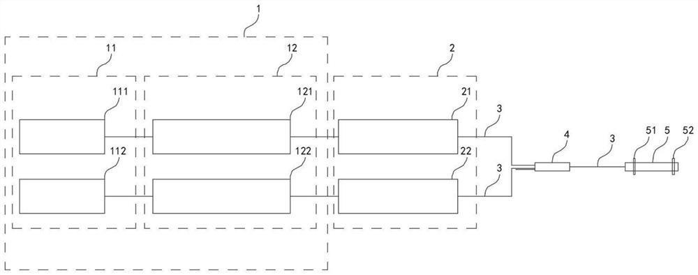
[0024] see Figure 1 to Figure 2 , a coaxial multi-channel laser transmitter, comprising a laser driving module 1, at least two laser generators 2, a plurality of light guiding fibers 3, an all-in-one fiber node 4 and a laser emitting head 5; the laser driving module 1 They are respectively connected with each laser generator 2, and each laser generator 2 is driven by the laser driving module 1 to generate laser light, and the laser wavelengths produced by each laser generator 2 are different; The input end of the all-in-one fiber node 4 is connected; the output end of the all-in-one fibe...


PUM

PropertyMeasurementUnit
wavelengthaaaaaaaaaa

Abstract

The invention discloses a coaxial multi-path laser transmitter and a coaxial laser transmitting device for simulating countermeasure. The coaxial multi-path laser transmitter comprises a laser driving module, at least two laser generators, a plurality of light guide optical fibers, an all-in-one optical fiber node and a laser transmitting head, the laser driving module is respectively connected with each laser generator, each laser generator is respectively driven by the laser driving module to generate laser, and the wavelengths of the laser generated by each laser generator are different; each laser generator is connected with the input end of the all-in-one optical fiber node through a light guide optical fiber; the output end of the all-in-one optical fiber node is connected with the laser emitting head through a light guide optical fiber, drives one laser generator and coaxially emits laser generated by the laser generator out of the laser emitting head; the coaxial multi-path laser transmitter is installed on a gun, and correction laser or shooting laser is coaxially emitted outwards from a gun barrel by driving the correction laser generator or the shooting laser generator.

Description

technical field [0001] The invention relates to the technical field of laser equipment, in particular to a coaxial multi-channel laser transmitter and a coaxial laser emitting device for simulating countermeasures. Background technique [0002] The aiming and hitting of guns follow the relationship between the line of sight, the ballistic line, and the axis of the fire body. In the process of shooting training or simulation exercises, some guns have adopted lasers to replace traditional ammunition. When the lasers on the guns hit the opponent's clothes or helmets, the system can show that the person was hit. However, in order to calibrate the gun, the existing guns are generally equipped with a calibration laser and a shooting laser respectively on the barrel, the calibration laser emitted by the calibration laser is used to calibrate the gun, and the shooting laser emitted by the shooting laser is used to hit the target. The existing calibration lasers and shooting lasers ...

Claims


Application Information

Patent Timeline
Patent Type & Authority Applications(China)
IPC IPC(8): F41G1/44F41A33/00
CPCF41G1/44F41A33/00
Inventor 张艳辉
Owner 张艳辉
Learn More