A Floating Filament Grid Modulator

A modulator and grid technology, which is applied in the field of floating filament grid modulators, can solve the problems of inadequate protection measures, complex implementation methods, and large volume, and achieve the effects of perfect protection measures, low power consumption, and small volume.

Active Publication Date: 2015-12-23
中国船舶重工集团公司第七二三研究所
View PDF2 Cites 0 Cited by
  • Summary
  • Abstract
  • Description
  • Claims
  • Application Information

AI Technical Summary

Problems solved by technology

[0004] In short, the existing floating filament grid modulator is too complicated to implement, resulting in large volume, high power consumption, long delay, and inadequate protection measures

Method used


Image

  • A Floating Filament Grid Modulator
  • A Floating Filament Grid Modulator
  • A Floating Filament Grid Modulator

Examples


Embodiment Construction

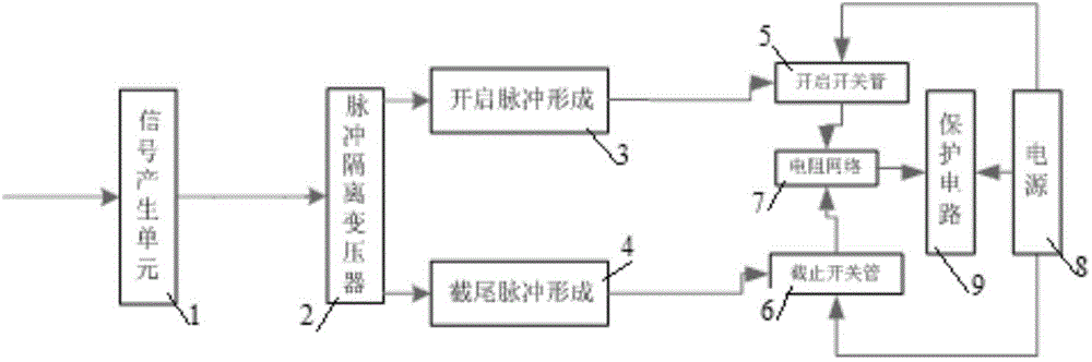
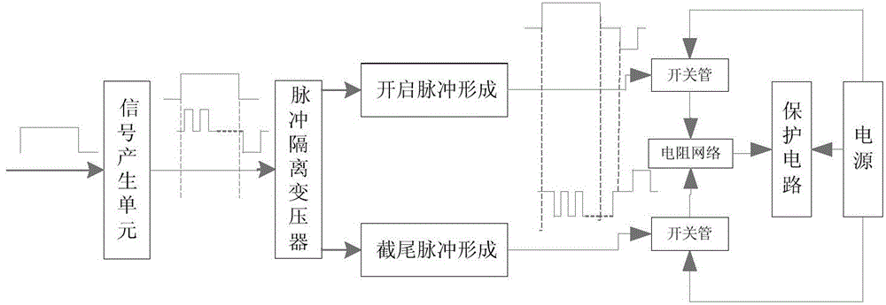
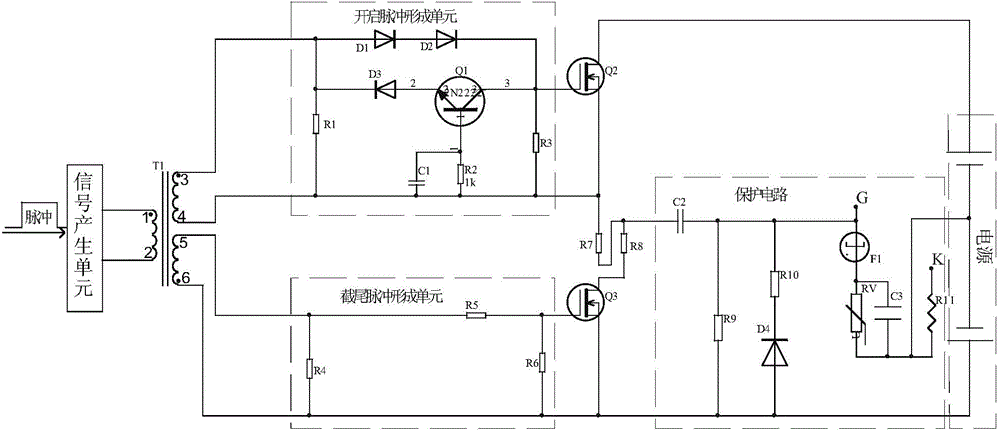
[0029] Such as figure 1 As shown, the floating filament grid modulator of the present invention includes:

[0030] A signal generating unit 1, configured to generate pulse signals, including leading edge pulses, trailing edge pulses and supplementary pulses;

[0031] Pulse isolation transformer 2, used to transmit pulse signals and isolate high and low voltage;

[0032] The opening pulse forming unit 3 is used to generate the opening pulse according to the leading edge pulse and the supplementary pulse;

[0033] A truncated pulse forming unit 4, configured to generate a truncated pulse according to the trailing edge pulse;

[0034] Turn on the MOS transistor 5 to turn on the turn-on voltage according to the turn-on pulse;

[0035] cut-off MOS transistor 6, used to turn on the cut-off voltage according to the truncated pulse;

[0036] Resistor network 7, used for current limiting and output voltage;

[0037] The power supply 8 is used to provide power for turning on the MO...


PUM


Abstract

The invention relates to a floating lamp filament grid modulator which comprises a signal generation unit, a pulse isolation transformer, a starting pulse formation unit, a chopping pulse formation unit, a starting MOS tube, a chopping MOS tube, a resistance network and a power source. The input end of the pulse isolation transformer is connected with the output end of the signal generation unit, the first output end of the pulse isolation transformer is connected with the input end of the starting pulse formation unit, the second output end of the pulse isolation transformer is connected with the input end of the chopping pulse formation unit, the grid of the starting MOS tube is connected with the output end of the starting pulse formation unit, the drain of the starting MOS tube is connected with the first output end of the power source, the source of the starting MOS tube is connected with the first input end of the resistance network, the grid of the chopping MOS tube is connected with the output end of the chopping pulse formation unit, the drain of the chopping MOS tube is connected with the second output end of the power source, the source of the chopping MOS tube is connected with the second input end of the resistance network, and the voltage is output from the output end of the resistance network. The floating lamp filament grid modulator is simple in achieving method, low in power dissipation, small in size and short in delayed time.

Description

technical field [0001] The invention belongs to the field of microwave power amplifiers, in particular to a floating filament grid modulator with low power consumption, small volume and short delay. Background technique [0002] The microwave power amplifier using the pulse traveling wave tube as the amplifying unit is mainly composed of two major units, the pulse traveling wave tube and the high voltage power supply, among which the floating filament grid modulator is one of the important components of the high voltage power supply, and its main function is two parts : Heating the hot wire of the traveling wave tube to make the cathode of the traveling wave tube reach the preset temperature; controlling the on-off of the electron beam to realize the opening and closing of the traveling wave tube. [0003] Usually, the filament or the grid needs to be regulated separately, especially the turn-on voltage regulation accuracy of switching the TWT state from the cut-off state to...

Claims


Application Information

Patent Timeline
Patent Type & Authority Patents(China)
IPC IPC(8): H01J23/34
Inventor 朱元江黎滨王磊高彧博毕磊梁雪松谢章贵王斌赵莉
Owner 中国船舶重工集团公司第七二三研究所
Why Eureka
Try Eureka