
Tower tube internal part welding-free column lapping testing mechanism

A testing mechanism, no welding technology, used in the testing of mechanical parts, the testing of machine/structural parts, measuring devices, etc., can solve the problems of inconvenient welding, affecting the stability of the installation structure, lack of testing equipment, etc., to improve the test effect. Effect

Pending Publication Date: 2022-07-22
中航试金石检测科技(大厂)有限公司
View PDF0 Cites 0 Cited by
  • Summary
  • Abstract
  • Description
  • Claims
  • Application Information

AI Technical Summary

Problems solved by technology

The electric energy generated by the wind turbine is generally transmitted through the bus bar. The multi-section bus bar is connected and installed vertically in the tower. When the bus bar is installed, the traditional method is to weld the column system in the tower tube, and then use the column system to The busbar is fixed, but there is some inconvenience in welding in the tower, and there are many disadvantages
[0003] In order to solve the inconvenience caused by welding, a non-welding form of fixing was developed. Due to the harsh operating environment of wind power, the vibration generated by the operation of the generator and the swing of the tower at different angles will cause varying degrees of damage to the connecting components. It will further affect the stability of the installation structure, so certain simulation experiments are required to test the fixation without welding, but there is a lack of corresponding testing equipment in the prior art

Method used


Image

  • Tower tube internal part welding-free column lapping testing mechanism
  • Tower tube internal part welding-free column lapping testing mechanism
  • Tower tube internal part welding-free column lapping testing mechanism

Examples


Embodiment Construction

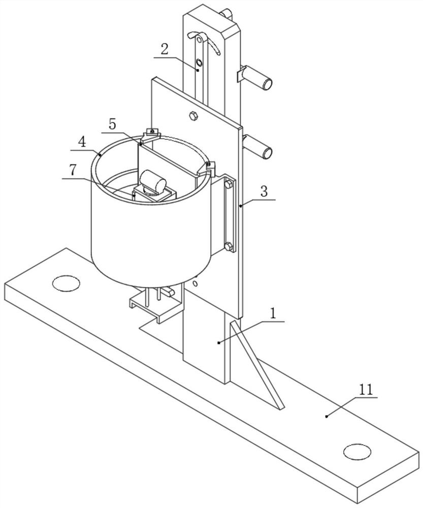
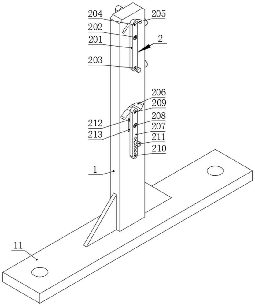
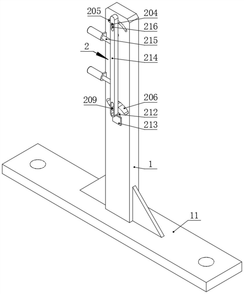
[0028] In this embodiment, a test mechanism for the non-welded lap column of the tower inner parts, please refer to figure 1 , Figure 5, including a vertical plate 1 and a bottom plate 11, the vertical plate 1 is vertically fixed on the bottom plate 11, an adjustable swing simulation mechanism 2 is installed on the vertical plate 1, and the swing end of the adjustable swing simulation mechanism 2 A swinging plate 3 is installed on the upper surface, a cylinder 4 is fixedly installed on the front of the swinging plate 3, a connecting plate 5 is installed in the cylinder 4, and a front surface of the connecting plate 5 is fixedly installed with a self-positioning fixing mechanism 6. Column 7, a vertical loading mechanism 8 is fixedly installed at the bottom of the column 7, a vibration motor 10 is installed on the top of the column 7, and the bottom end of the vertical loading mechanism 8 is connected to the connection plate 5. The bottom is fixedly connected, a swing loading ...


PUM


Abstract

The invention discloses a tower internal part welding-free column lapping testing mechanism which comprises a vertical plate and a bottom plate, the vertical plate is vertically and fixedly installed on the bottom plate, an adjustable swing simulation mechanism is installed on the vertical plate, a swing plate is installed at the swing end of the adjustable swing simulation mechanism, a cylinder is fixedly installed on the front face of the swing plate, and the cylinder is fixedly installed on the back face of the cylinder. And a connecting plate is installed in the cylinder, and a lapping column is fixedly installed on the front face of the connecting plate through a self-positioning fixing mechanism. According to the invention, by arranging the adjustable swing simulation mechanism, the swing of the tower drum at different heights and different amplitudes can be simulated, the real condition of the tower drum can be simulated to the greatest extent, a column erecting system can be conveniently tested, and during loading by using a steel rope, the vertical loading mechanism shakes left and right without rigid limitation and can slightly shake within a certain range; therefore, when the adjustable swing simulation mechanism swings, the weight and inertia of the hydraulic cylinder are utilized to apply an alternating load to the lapping column and the self-positioning fixing mechanism.

Description

technical field [0001] The invention relates to the technical field of installation structure testing. Specifically, it is a non-welded lap test mechanism for tower inner parts. Background technique [0002] Wind power generation refers to the use of the kinetic energy of the wind to generate electricity, and the use of a tower to fix the wind turbine at a certain height to generate electricity. The electric energy generated by the wind turbine is generally transmitted through the busbar. The multi-section busbar is butted and installed vertically in the tower. When the busbar is installed, the traditional method is to weld the column system in the tower, and then use the column system to The busbar is fixed, but welding in the tower is inconvenient and has many disadvantages. [0003] In order to solve the inconvenience caused by welding, a fixed form without welding has been developed. Due to the harsh operating environment of wind power, the vibration generated by the o...

Claims


Application Information

Patent Timeline
Patent Type & Authority Applications(China)
IPC IPC(8): G01M13/00
CPCG01M13/00
Inventor 周峰峦赵昀郑丽玲林晓亮李宏峰梁博
Owner 中航试金石检测科技(大厂)有限公司
Learn More