Rolling magnet type three-stable-state electromagnetic energy collecting device

An electromagnetic energy collection device technology, applied in the direction of electromechanical devices, electrical components, etc., can solve problems such as the impact of energy capture efficiency, and achieve the effect of improving power generation efficiency, small limitation, and high sensitivity

Pending Publication Date: 2022-07-22
ZHENGZHOU UNIV
View PDF0 Cites 0 Cited by
  • Summary
  • Abstract
  • Description
  • Claims
  • Application Information

AI Technical Summary

Problems solved by technology

However, the frequency of environmental vibration is mostly distributed in a wide frequency band and has a certain degree of randomness. When the linear system is used in this case, its energy capture efficiency will be greatly affected, and it has become a restrictive electromagnetic vibration energy capture technology. development bottleneck

Method used


Image

  • Rolling magnet type three-stable-state electromagnetic energy collecting device
  • Rolling magnet type three-stable-state electromagnetic energy collecting device
  • Rolling magnet type three-stable-state electromagnetic energy collecting device

Examples


Embodiment 1

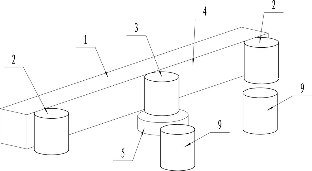
[0035] like figure 1 , figure 2 and Image 6 As shown, a rolling magnet type tri-stable electromagnetic energy collection device includes a fixed magnet 1, two limit magnets 2, a moving magnet 3, two modulation magnets 9 and a coil 5;

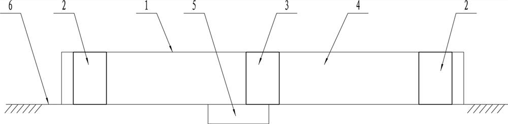
[0036] The fixed magnet 1 is configured as a long strip, and one of the long sides of the fixed magnet 1 is used as the moving track 4. In this embodiment, one of the vertical sides of the fixed magnet 1 is used as the moving track 4, and the lower part of the fixed magnet is arranged The support structure 6, such as the support plane, acts as a limit surface or a support surface for the movement of the moving magnet.

[0037] The two limit magnets 2 are configured to be disposed at the head and tail ends of the moving track 4 of the fixed magnet 1 respectively, and their main function is to limit the travel range of the moving magnet.

[0038] The two modulating magnets 9 are arranged parallel to the moving track 4, the center line is para...

Embodiment 2

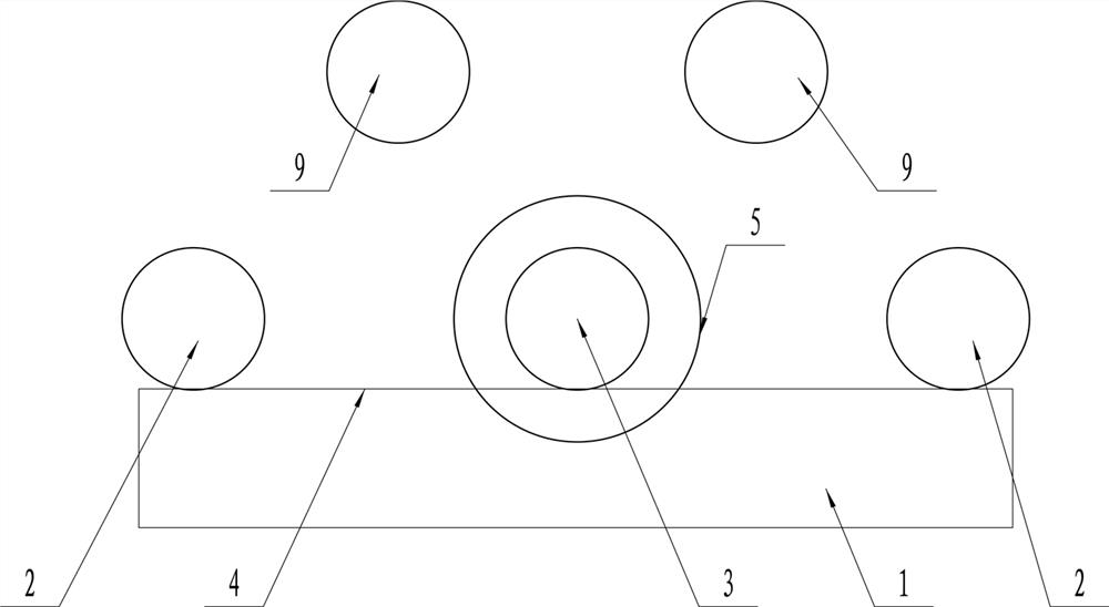
[0043] like image 3 As shown, in this embodiment, in order to optimize the performance of the device, the moving magnet 3, the two limit magnets 2 and the modulation magnet 9 are set as cylinders, and the moving magnet 3, the two limit magnets 2 and the modulation magnet 9 are set as cylinders. The diameters of the magnets are the same, the moving magnets 3 and the moving track 4 are in rolling fit, and the thickness of the moving magnets 3 is equal to the thickness of the fixed magnets 1 .

[0044] The fixed magnet 1 is a rectangular elongated structure, one of the vertical sides of the fixed magnet 1 is used as a moving track, and the bottom end of the moving track 4 is provided with a support structure 6 that supports the movement of the moving magnet. In this embodiment, the structure 6 is a flat supporting surface, the coil 5 is embedded in the supporting surface, and the axis of the coil 5 passes through the movement track of the moving magnet 3 .

[0045] In other emb...

Embodiment 3

[0047] like Figure 4 and Figure 5 As shown, the opposite side of the motion track 4 is provided with a guardrail 7 to limit the displacement of the motion magnet. The guardrail 7, the supporting structure 6, the motion track 4 and the two limit magnets 2 form a closed motion space. The moving magnet is located in the moving space, the modulation magnet 9 can be installed on the basis of the guardrail 7, and the distance between it and the moving track 4 can be adjusted along the adjustment slot set on the guardrail 7. This structure can be adapted to more The application environment is less restricted, and the external stimulus can also be directly applied to the external structure ( Figure 4 Due to the problem of viewing angle, the modulation magnet is not drawn in the middle, which does not affect the expression of meaning).

[0048] Preferably, the vacant surface of the motion space is provided with an end cover. By completely enclosing the motion magnet in the closed ...


PUM


Abstract

The invention provides a rolling magnet type three-stable-state electromagnetic energy collecting device. The rolling magnet type three-stable-state electromagnetic energy collecting device comprises a fixed magnet, two limiting magnets, a moving magnet, two modulation magnets and a coil. The fixed magnet is strip-shaped, and one long side of the fixed magnet is used as a motion track; the two limiting magnets are arranged at the head end and the tail end of the fixed magnet movement track respectively. The two modulation magnets are parallel to the motion track, the center connecting line is parallel to the fixed magnet, and the distance between the two modulation magnets and the center of the fixed magnet is equal; all the magnets are arranged in a plane, the moving magnet is configured to only move along a moving track, the moving magnet and the fixed magnet are attractive, and the moving magnet, the limiting magnet and the modulation magnet are repulsive; the coil is arranged on one side of the motion track and is externally connected with a current leading-out port. The energy acquisition structure can realize the three-stable-state characteristic, and has the advantages of wide response frequency band, high sensitivity, easiness in adjustment and the like.

Description

technical field [0001] The invention relates to the technical field of electromagnetic vibration energy capture, in particular to a rolling magnet type tri-stable electromagnetic energy collection device. Background technique [0002] Power supply networks for sensors and data transmission are widely used in industrial process and health monitoring fields. In the traditional energy supply method, a power connection through a wire or a battery replacement is necessary. Since all measurement points require wiring, this method is very expensive. Recent developments in the field of health monitoring include minimizing the number of sensors and minimizing power consumption, however maintaining the energy supply remains a difficult issue and may require the use of additional equipment. In this context, harnessing ambient energy to power sensors has received much attention. [0003] Using a certain method to convert various forms of energy in the environment into electrical ener...

Claims


Application Information

Patent Timeline
Patent Type & Authority Applications(China)
IPC IPC(8): H02K35/02
CPCH02K35/02
Inventor 王伟卫洪涛胡志鑫卫荣汉
Owner ZHENGZHOU UNIV
Why Eureka
Try Eureka