Rolling magnet type monostable electromagnetic energy capturing device

An electromagnetic energy, monostable technology, applied in the direction of electromechanical devices, electrical components, etc., can solve the problems of narrow frequency band of linear structure, influence of energy capture performance, etc., to achieve high sensitivity, improve energy capture efficiency, and improve power generation efficiency.

Pending Publication Date: 2022-07-08
ZHENGZHOU UNIVERSITY OF AERONAUTICS
View PDF0 Cites 0 Cited by
  • Summary
  • Abstract
  • Description
  • Claims
  • Application Information

AI Technical Summary

Problems solved by technology

[0008] However, the frequency band of the linear structure is very narrow, and when the external excitation frequency shifts from the natural frequency, the energy capture performance will be greatly affected

Method used


Image

  • Rolling magnet type monostable electromagnetic energy capturing device
  • Rolling magnet type monostable electromagnetic energy capturing device
  • Rolling magnet type monostable electromagnetic energy capturing device

Examples


Embodiment 1

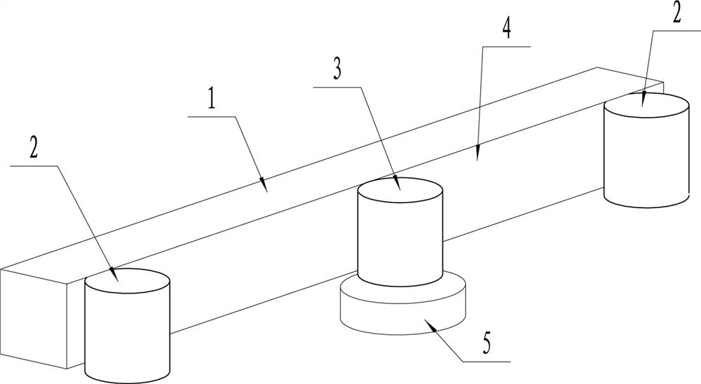
[0038] like figure 1 and figure 2 As shown, a rolling magnet type monostable electromagnetic energy capture device includes a fixed magnet 1, two limit magnets 2, a moving magnet 3 and a coil 5;

[0039] The fixed magnet 1 is configured as a long strip, and one of the long sides of the fixed magnet 1 is used as the moving track 4. In this embodiment, one of the vertical sides of the fixed magnet 1 is used as the moving track 4, and the lower part of the fixed magnet is arranged The support structure 6, such as the support plane, serves as a limit surface or a support surface for the movement of the moving magnet.

[0040] The two limit magnets 2 are configured to be disposed at the head and tail ends of the moving track 4 of the fixed magnet 1 respectively, and their main function is to limit the travel range of the moving magnet.

[0041] The moving magnet 3 is configured to be able to move only along the moving track 4. There is an attractive force between the moving magn...

Embodiment 2

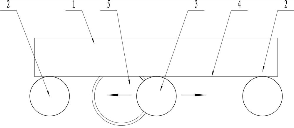
[0047] like image 3 As shown, in this embodiment, in order to optimize the performance of the device, the moving magnet 3 and the two limit magnets 2 are set as cylinders, and the diameters of the moving magnet 3 and the two limit magnets 2 are equal. The moving magnet 3 is in rolling fit with the moving track 4 , and the thickness of the moving magnet 3 is equal to the thickness of the fixed magnet 1 .

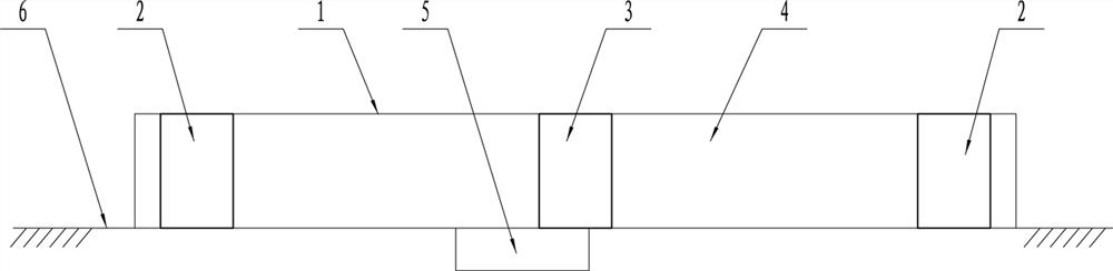
[0048]The fixed magnet 1 is a rectangular elongated structure. One of the vertical sides of the fixed magnet 1 is used as a moving track. The bottom end of the moving track 4 is provided with a support structure 6 that supports the movement of the moving magnet. In this embodiment, the structure 6 is a flat supporting surface, the coil 5 is embedded in the supporting surface, and the axis of the coil 5 passes through the movement track of the moving magnet 3 .

Embodiment 3

[0050] like Figure 4 As shown, the opposite side of the motion track 4 is provided with a guardrail 7 to limit the displacement of the motion magnet. The guardrail 7, the supporting structure 6, the motion track 4 and the two limit magnets 2 form a closed motion space. The moving magnet is located in the moving space. This structure can adapt to more application environments and is less restricted. The external excitation can also be directly applied to the external structure.

[0051] Preferably, the vacant surface of the motion space is provided with an end cover. By completely enclosing the motion magnet in the closed space, the device can be applied to a wider range of applications, such as power supply of portable electronic components.

[0052] In other embodiments, the fixed magnet may be a long structure with an arc, and the movable track of the fixed magnet is designed as the top surface, and the moving magnet 3 will also be affected by its own gravity to produce a r...


PUM


Abstract

The invention provides a rolling magnet type monostable electromagnetic energy capturing device. The rolling magnet type monostable electromagnetic energy capturing device comprises a fixed magnet, two limiting magnets, a moving magnet and a coil, the fixed magnet is configured to be in a long strip shape, and one long side of the fixed magnet serves as a motion track. The two limiting magnets are arranged at the head end and the tail end of the fixed magnet movement track respectively; all the magnets are arranged in the same plane, the moving magnet is configured to only move along the moving track, the moving magnet and the fixed magnet are attractive, and the moving magnet and the two limiting magnets are repulsive; the coil is configured to be arranged on one side of the motion track, and the motion track of the motion magnet passes through one end of the coil so that induction current can be generated in the coil. The rolling magnet type monostable electromagnetic energy capturing device has the advantages of wide response frequency band, simple structure, long service life and the like.

Description

technical field [0001] The invention relates to the technical field of electromagnetic vibration energy capture, in particular to a rolling magnet monostable electromagnetic energy capture device. Background technique [0002] With the rapid development of low-power and high-performance microprocessors and micro-sensing technologies, a large number of wireless sensors are applied to important occasions such as health monitoring, equipment status monitoring, and battlefield situational awareness. These devices can feed back the status information of the monitored objects in real time, effectively improving the response speed to emergency events. [0003] In addition, the rapid development of human wearable technology has prompted a large number of portable electronic devices and embedded health monitoring devices to be applied to people's daily life. These devices can monitor the movement state of the human body in real time and effectively prevent the occurrence of major dis...

Claims


Application Information

Patent Timeline
IPC IPC(8): H02K35/02
CPCH02K35/02
Inventor 刘双燕李勇周博耿直刘海斌
Owner ZHENGZHOU UNIVERSITY OF AERONAUTICS
Why Eureka
Try Eureka