Pipe end expanding and forming device

A technology of forming device and pipe end, which is applied in the field of pipe end expanding and forming device, can solve the problems of manual work, which cannot be applied to various types of steel pipes and pipe expanding, etc.

Pending Publication Date: 2022-07-26
海宁红狮宝盛科技有限公司
View PDF8 Cites 2 Cited by
  • Summary
  • Abstract
  • Description
  • Claims
  • Application Information

AI Technical Summary

Problems solved by technology

[0003] Although the above comparison documents are convenient for loading materials, they cannot be applied to various types of steel pipes for pipe expansion. In addition, when blanking, manual blanking is required

Method used


Image

  • Pipe end expanding and forming device
  • Pipe end expanding and forming device
  • Pipe end expanding and forming device

Examples


Embodiment Construction

[0018] The technical solutions in the embodiments of the present invention will be clearly and completely described below with reference to the accompanying drawings in the embodiments of the present invention. Obviously, the described embodiments are only a part of the embodiments of the present invention, but not all of the embodiments. Based on the embodiments of the present invention, all other embodiments obtained by those of ordinary skill in the art without creative efforts shall fall within the protection scope of the present invention.

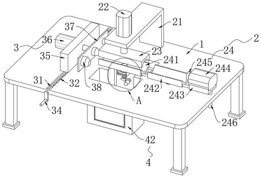
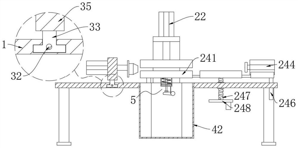
[0019] See e.g. figure 1 , image 3 As shown, the present invention provides a technical solution: a pipe end expanding and forming device, comprising a worktable 1, and a steel pipe positioning mechanism 2 is arranged above the worktable 1 to facilitate pipe feeding and clamping. The steel pipe positioning mechanism 2. It includes an L-shaped frame 21 fixed on the upper end of the worktable 1, a cylinder 1 22 is arranged above the L...


PUM


Abstract

The invention relates to the technical field of metal pipe machining, in particular to a pipe end expanding and forming device. According to the technical scheme, the pipe expanding device comprises a working table plate, a steel pipe positioning mechanism facilitating pipe feeding and clamping is arranged above the working table plate, a pipe expanding mechanism facilitating pipe expanding is arranged on the left side of the steel pipe positioning mechanism, a storage assembly facilitating pipe storage is arranged on the working table plate, and a discharging mechanism facilitating pipe discharging is arranged in the storage assembly. The pipe expanding equipment is improved, so that the pipe expanding equipment is suitable for expanding steel pipes of various models, meanwhile, the expanded steel pipes can be automatically discharged conveniently, and pipe expanding work is further facilitated.

Description

technical field [0001] The invention relates to the technical field of metal pipe processing, in particular to a pipe end expanding and forming device. Background technique [0002] The existing Chinese patent with the authorization announcement number CN215033028U discloses a pipe expansion device at the end of a steel pipe. By arranging a storage box and a first cylinder, the steel pipe is pushed from the storage box to the fixed die by the first cylinder. The feeding process of the steel pipe is changed to push, so as to reduce human labor; by setting the vibration motor on the storage box, when the steel pipes in the storage box overlap each other, the vibration motor makes the storage box vibrate, making the steel pipe smooth Drop from the bottom of the storage box to the piston rod of the first cylinder; by setting the storage box as a movable plate and a fixed plate, and slidingly connecting the movable plate and the fixed plate, the size of the storage box can be pas...

Claims


Application Information

Patent Timeline
Patent Type & Authority Applications(China)
IPC IPC(8): B21D41/02B21D43/00B21D43/20B21D45/00
CPCB21D41/02B21D43/003B21D45/00B21D43/20
Inventor 余刘建吴式胜邓樊凡徐斌
Owner 海宁红狮宝盛科技有限公司
Why Eureka
Try Eureka