Processing device and processing method of permanent magnet motor rotor

A technology for permanent magnet motors and processing devices, which is applied in the direction of grinding drive devices, metal processing equipment, and parts of grinding machine tools. Motor rotor efficiency and other issues to achieve the effect of improving efficiency and convenience

Pending Publication Date: 2022-03-01
赣州诚正电机有限公司
View PDF0 Cites 1 Cited by
  • Summary
  • Abstract
  • Description
  • Claims
  • Application Information

AI Technical Summary

Problems solved by technology

[0003] 1. When the existing technology is processing the motor rotor, most of the motor rotors to be processed are placed manually, and the automatic feeding of the motor rotor cannot be realized. When the motor rotor needs to be processed in batches, the efficiency of processing the motor rotor is affected;
[0004] 2. In the existing technology, the fixed clamping of the motor rotor is mostly realized through a complex clamping mechanism, which makes the fixed clamping of the motor rotor relatively inconvenient;
[0005] 3. Most of the existing technologies are unable to grind the motor rotor in the rotating state when processing the motor rotor, which leads to poor grinding effect of the motor rotor. Therefore, we propose a permanent magnet motor The rotor processing device and processing method are used to solve the above problems

Method used


Image

  • Processing device and processing method of permanent magnet motor rotor
  • Processing device and processing method of permanent magnet motor rotor
  • Processing device and processing method of permanent magnet motor rotor

Examples


Embodiment

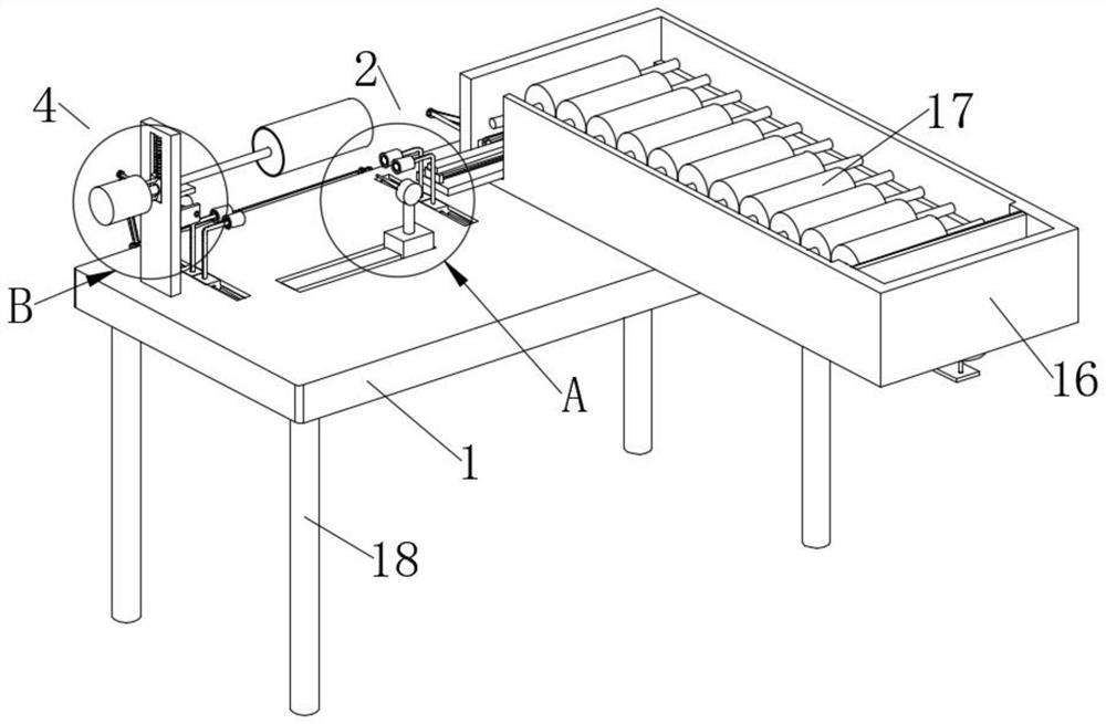
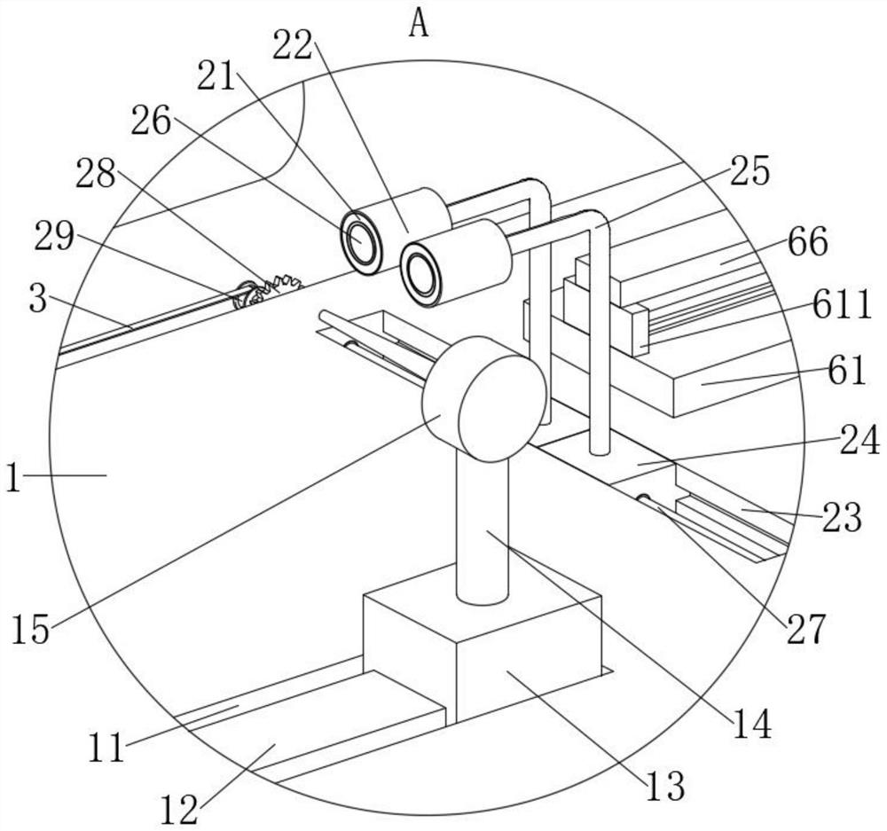
[0045] Example: such as Figure 1-13 As shown, the present invention provides a processing device for a permanent magnet motor rotor, comprising a processing table 1 and a rotor body 17, the upper surface of the processing table 1 is provided with a notch 11, and the inner wall of the notch 11 is fixedly equipped with a linear electric cylinder 12 , the surface of the linear electric cylinder 12 is slidably connected with a slider 13, by opening the linear electric cylinder 12, the linear electric cylinder 12 can drive the slider 13 to slide horizontally, and the side of the slider 13 away from the linear electric cylinder 12 is fixedly installed with a moving rod 14 A grinding machine 15 is fixedly installed on the end of the moving rod 14 away from the slider 13, the slider 13 can move the grinding machine 15 horizontally through the moving rod 14, and the rotor body 17 can be processed by opening the grinding machine 15. The upper surface of the table 1 is fixed with a disc...


PUM


Abstract

The invention discloses a machining device and a machining method for a permanent magnet motor rotor, belongs to the technical field of rotor machining, and solves the problem that in the prior art, when the rotor is machined, most rotors in a rotating state cannot be ground, so that the grinding effect of the motor rotor is poor. A notch is formed in the upper surface of the machining table, a linear electric cylinder is fixedly mounted on the inner wall of the notch, a sliding block is slidably connected to the surface of the linear electric cylinder, and a moving rod is fixedly mounted on the face, away from the linear electric cylinder, of the sliding block; a rotating roller is driven to rotate, the rotating roller enables the fixed rotor body to rotate through friction force, a linear electric cylinder and a grinding machine are started, a sliding block enables the grinding machine to move through a moving rod, the grinding machine conducts grinding machining on the outer wall of the rotor body in the rotating state, and therefore machining of the rotor body is conveniently completed. And therefore, the convenience of machining the rotor body is effectively improved, and the grinding machining effect of the rotor body is effectively improved.

Description

technical field [0001] The invention relates to the technical field of rotor processing, in particular to a processing device and a processing method for a permanent magnet motor rotor. Background technique [0002] Motor rotor: Also the rotating part in the motor. The motor consists of two parts, the rotor and the stator, which are used to realize the conversion of electrical energy and mechanical energy and mechanical energy and electrical energy. The motor rotor is divided into a motor rotor and a generator rotor. The existing technology has the following problems when processing the motor rotor: [0003] 1. When the existing technology is processing the motor rotor, most of the motor rotors to be processed are placed manually, and the automatic feeding of the motor rotor cannot be realized. When the motor rotor needs to be processed in batches, the efficiency of processing the motor rotor is affected; [0004] 2. In the existing technology, the fixed clamping of the m...

Claims


Application Information

Patent Timeline
Patent Type & Authority Applications(China)
IPC IPC(8): B24B5/36B24B5/35B24B41/06B24B27/02B24B47/04H02K15/02
CPCB24B5/363B24B5/355B24B41/067B24B27/02B24B47/04H02K15/02
Inventor 赖诚明朱慧赖正泷王安兵赖正波
Owner 赣州诚正电机有限公司
Why Eureka
Try Eureka