Preheating method before friction stir welding

A friction stir and welding bead technology, applied in welding equipment, non-electric welding equipment, metal processing equipment, etc., can solve the problems of increasing welding speed limit, large welding axial force, affecting welding efficiency, etc., to reduce welding difficulty and prolong Long service life, easy high-speed welding effect

Pending Publication Date: 2022-07-26
昆山六丰机械工业有限公司
View PDF0 Cites 0 Cited by
  • Summary
  • Abstract
  • Description
  • Claims
  • Application Information

AI Technical Summary

Problems solved by technology

Therefore, during the welding process, there are problems such as serious wear of the stirring head and large welding axial force. At the same time, it also limits the increase in welding speed and affects welding efficiency.

Method used


Image

  • Preheating method before friction stir welding

Examples


Embodiment 1

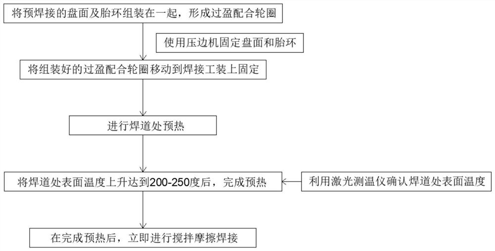
[0024] see figure 1 , the present invention provides a technical scheme: a preheating method for friction stir welding, comprising the following steps:

[0025] S1. Assemble the pre-welded disc surface and tire ring together to form an interference fit rim;

[0026] S2. Move the assembled interference fit rim to the welding tool to fix it, and use the edge holder to fix the disc surface and the tire ring;

[0027] S3. Preheat the weld bead;

[0028] S4. Use a laser thermometer to confirm the surface temperature of the weld bead. After reaching 200 degrees, complete the preheating;

[0029] S5. After preheating is completed, friction stir welding is performed immediately.

[0030] In this embodiment, preferably, before the disk surface and the tire ring are assembled together in S1, the disk surface and the tire ring are further cleaned to remove impurities and oil stains on the disk surface and the tire ring surface.

[0031] In this embodiment, preferably, the specific me...

Embodiment 2

[0048] see figure 1 , the present invention provides a technical scheme: a preheating method for friction stir welding, comprising the following steps:

[0049] S1. Assemble the pre-welded disc surface and tire ring together to form an interference fit rim;

[0050] S2. Move the assembled interference fit rim to the welding tool to fix it, and use the edge holder to fix the disc surface and the tire ring;

[0051] S3. Preheat the weld bead;

[0052] S4. Use a laser thermometer to confirm the surface temperature of the weld bead. After reaching 250 degrees, complete the preheating;

[0053] S5. After preheating is completed, friction stir welding is performed immediately.

[0054] In this embodiment, preferably, before the disk surface and the tire ring are assembled together in S1, the disk surface and the tire ring are further cleaned to remove impurities and oil stains on the disk surface and the tire ring surface.

[0055] In this embodiment, preferably, the specific me...

Embodiment 3

[0072] see figure 1 , the present invention provides a technical scheme: a preheating method for friction stir welding, comprising the following steps:

[0073] S1. Assemble the pre-welded disc surface and tire ring together to form an interference fit rim;

[0074] S2. Move the assembled interference fit rim to the welding tool to fix it, and use the edge holder to fix the disc surface and the tire ring;

[0075] S3. Preheat the weld bead;

[0076] S4. Use a laser thermometer to confirm the surface temperature of the weld bead. After reaching 220 degrees, complete the preheating;

[0077] S5. After preheating is completed, friction stir welding is performed immediately.

[0078] In this embodiment, preferably, before the disk surface and the tire ring are assembled together in S1, the disk surface and the tire ring are further cleaned to remove impurities and oil stains on the disk surface and the tire ring surface.

[0079] In this embodiment, preferably, the specific me...


PUM


Abstract

The invention discloses a method for preheating before friction stir welding, which comprises the following steps of: S1, assembling a disc surface and a tire ring which are pre-welded together to form an interference fit rim; s2, the assembled interference fit rim is moved to a welding tool to be fixed; s3, preheating at a welding bead; s4, determining the surface temperature of the weld bead by using a laser thermometer, and completing preheating after the surface temperature reaches 200-250 DEG C; and S5, after preheating is completed, friction stir welding is conducted immediately. By means of preheating assistance, the welding heat input amount can be increased, welding materials can be softened, the requirement for downward pressure is lowered, meanwhile, the welding difficulty can be lowered, abrasion of the stirring head is reduced, the service life of the stirring head is prolonged, the welding axial force and the welding difficulty of high-melting-point metal are lowered, high-speed welding is easy to achieve, and the welding efficiency is improved. And in addition, a proper preheating temperature is adopted, so that the material generates good plastic flow, and the generation of defects such as tunnel holes is avoided.

Description

technical field [0001] The invention belongs to the technical field of friction stir welding, and particularly relates to a preheating method before friction stir welding. Background technique [0002] In recent years, friction stir welding has been widely used in the welding of various metal materials, especially when welding light metal materials with low melting point and high performance. Compared with traditional fusion welding, friction stir welding is a solid phase welding. Compared with the low temperature of fusion welding, it can avoid defects such as burning of alloy elements, pores, cracks, etc., and the degree of welding deformation is small, and joints with good quality can also be obtained. The principle of friction stir welding is to use the stirring head to press down on the surface of the welding workpiece, so that the shoulder of the stirring head and the stirring needle are in close contact, and the stirring head rotates at a high speed to produce severe ...

Claims


Application Information

Patent Timeline
Patent Type & Authority Applications(China)
IPC IPC(8): B23K20/12B23K20/24B23K20/26
CPCB23K20/12B23K20/122B23K20/24B23K20/26
Inventor 宗绪惠魏授桐范纲衔路建琦何浚恺沈湘岚
Owner 昆山六丰机械工业有限公司
Why Eureka
Try Eureka