Supercharge Your Innovation With Domain-Expert AI Agents!

Rubber sealing ring production and collection device

A rubber sealing ring, collecting device technology, applied in transportation and packaging, conveyor objects, conveyors, etc., can solve problems such as unfavorable processing, high temperature, burns, etc.

Pending Publication Date: 2022-07-26
安徽龙行密封件有限公司
View PDF0 Cites 0 Cited by
  • Summary
  • Abstract
  • Description
  • Claims
  • Application Information

AI Technical Summary

Problems solved by technology

[0003] In the prior art, the rubber sealing ring is manually taken out after injection molding, and its temperature is high, which is easy to cause burns, and the sealing ring is often placed chaotically after collection, which is not conducive to subsequent processing. Therefore, the present invention proposes a solution that can solve the above problems A rubber sealing ring production and collection device

Method used


Image

  • Rubber sealing ring production and collection device
  • Rubber sealing ring production and collection device
  • Rubber sealing ring production and collection device

Examples


Embodiment 1

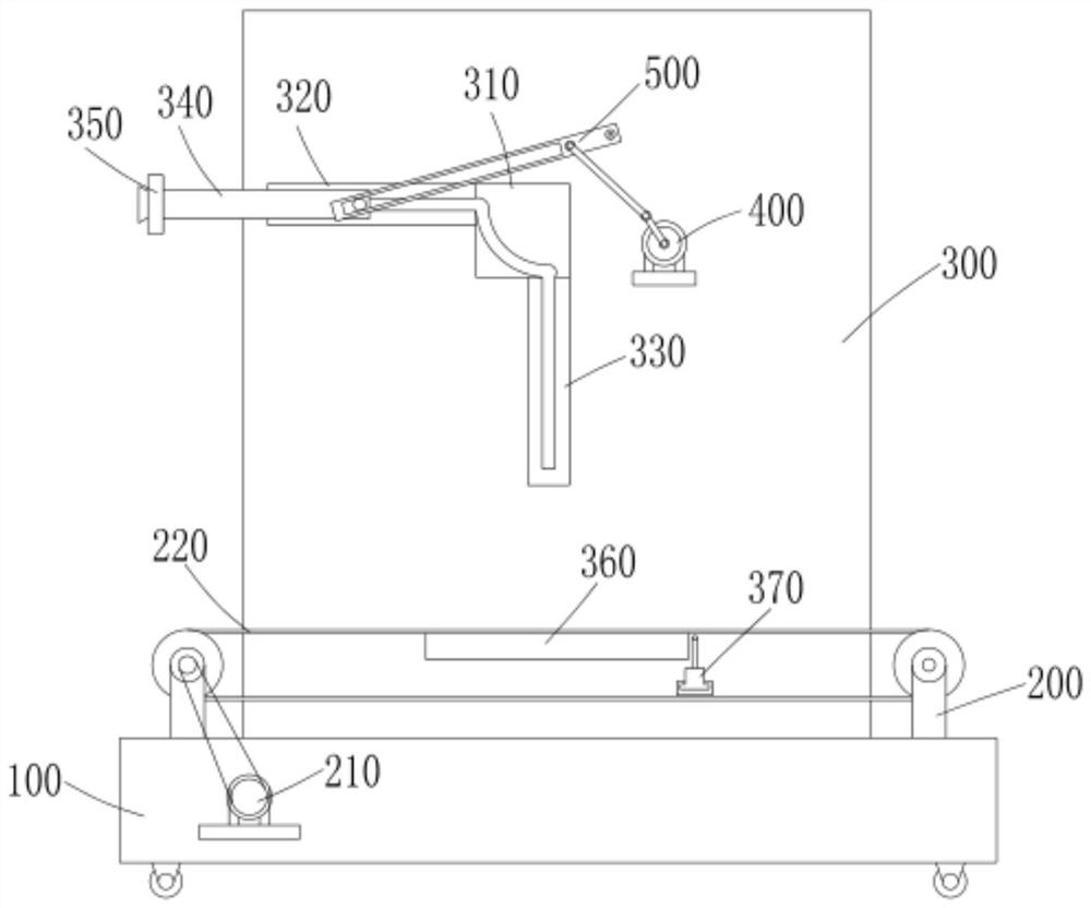
[0031] The present invention provides a technical solution: a rubber sealing ring production and collection device, comprising a base 100, a shelf plate 300, a movable plate 340 and a driving mechanism, a conveying mechanism 200 is installed on the base 100, and the conveying mechanism 200 includes a conveying belt group 220 and The first drive source 210 is used for intermittently driving the conveyor belt group 220 to operate; the shelf plate 300 is fixed on the rear side of the base 100, the front side of the shelf plate 300 is fixed with a support block, and the front end of the support block is provided with a fixed plate 310, a horizontal plate 320 is connected to the left side of the fixed plate 310, a horizontal slot 321 is arranged on the horizontal plate 320, a vertical plate 330 is connected to the lower side of the fixed plate 310, a vertical slot 331 is arranged on the vertical plate 330, and a vertical plate 331 is arranged on the fixed plate 310. Turning slot 311...

Embodiment 2

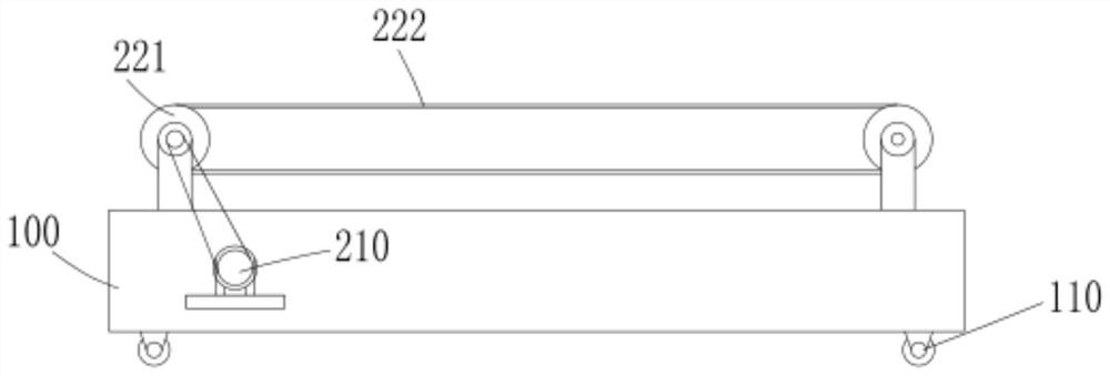
[0034] On the basis of Embodiment 1, the conveyor belt group 220 includes two sets of rotating rollers 221 and conveyor belts 222, and the conveyor belts 222 are sleeved on the two sets of rotating rollers 221; The components are several sets of collection grooves 2221 arranged on the conveyor belt 222, and the collection grooves 2221 correspond to the suction nozzles 351 one by one; the collection grooves 2221 are through grooves, and the front side of the shelf plate 300 is provided with a cooling plate 360, and the cooling plate 360 ​​is forward It extends to the middle of the conveyor belt and contacts the upper side of the conveyor belt 222 for cooling the rubber sealing ring placed in the collecting tank 2221; the front side of the shelf plate 300 is fixed with a backing plate 370, and the upper side of the backing plate 370 is slidably connected to move The seat 371 and the upper end of the movable seat 371 are provided with several sets of sleeve rods 372, and the sleev...

Embodiment 3

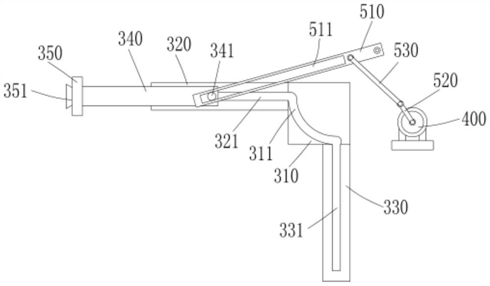
[0037] On the basis of Embodiment 1 or Embodiment 2, the transmission assembly 500 includes a driving arm 510, a first rotating arm 520 and a second rotating arm 530. One end of the driving arm 510 is hinged with the frame plate 300, and a guide is provided on the driving arm 510. Slot 511, the clamping block 341 is slidably connected with the guide groove 511, one end of the first rotating arm 520 is rotatable with the output shaft of the second driving source 400, one end of the second rotating arm 530 is rotatably connected with the driving arm 510, the first rotating arm 520 and the second The rotating arm 530 is hinged.

[0038] Specifically, when the second driving source 400 rotates, the first rotating arm 520 and the second rotating arm 530 drive the driving arm 510 to move on the frame plate 300 , and the driving arm 510 is engaged with the clamping block 341 through the driving slot to drive the movement. The plate 340 reciprocates along the movable groove, so that t...


PUM


Abstract

The invention discloses a rubber sealing ring production collecting device which comprises a base, a frame plate, a movable plate and a driving mechanism, a conveying mechanism is installed on the base and comprises a conveying belt set and a first driving source, and the first driving source is used for intermittently driving the conveying belt set to operate; the frame plate is fixedly connected to the rear side of the base, the supporting block is fixedly connected to the front side of the frame plate, the fixing plate is arranged at the front end of the supporting block, the transverse plate is connected to the left side of the fixing plate, the transverse groove is formed in the transverse plate, the vertical plate is connected to the lower side of the fixing plate, the vertical groove is formed in the vertical plate, and the steering groove is formed in the fixing plate, is an arc-shaped groove and is communicated with the transverse groove and the vertical groove. The steering groove, the transverse groove and the vertical groove form a movable groove; the movable plate is arranged on the front side of the frame plate, a clamping block is arranged at one end of the movable plate and slidably connected with the movable groove, and a suction cup is installed at the other end of the movable plate. The rubber sealing rings do not need to be manually taken by mouths, so that the rubber sealing rings are prevented from being scalded by high temperature, and the rubber sealing rings are tidily arranged on the conveying belt group to be conveyed.

Description

technical field [0001] The invention relates to the technical field of rubber sealing ring production, in particular to a rubber sealing ring production and collection device. Background technique [0002] The rubber sealing ring is an annular cover composed of one or several parts, which is fixed on one ring or washer of the bearing and contacts with another ring or washer or forms a narrow labyrinth gap to prevent the leakage of lubricating oil and the intrusion of foreign objects. [0003] In the prior art, the rubber sealing ring is manually taken out after injection molding, and its temperature is high, which is easy to cause burns, and the sealing ring is often placed in disorder after collection, which is not conducive to subsequent processing. Therefore, the present invention proposes a solution that can solve the above problems. A rubber sealing ring production collection device. SUMMARY OF THE INVENTION [0004] The purpose of the present invention is to provide...

Claims


Application Information

Patent Timeline
IPC IPC(8): B65G47/91B65G47/26B65G15/58
CPCB65G47/917B65G47/26B65G15/58
Inventor 彭常龙
Owner 安徽龙行密封件有限公司
Features
  • R&D
  • Intellectual Property
  • Life Sciences
  • Materials
  • Tech Scout
  • Unparalleled Data Quality
  • Higher Quality Content
  • 60% Fewer Hallucinations
Learn More