Multifunctional collating machine

A collating machine and multi-functional technology, applied in the field of multi-functional collating machines, can solve the problems of disjointness, paper wrinkle, increased pulling difficulty, etc., and achieve the effects of avoiding the use of compressors, reducing large resistance and saving costs.

Pending Publication Date: 2022-07-26
上海伊诺尔实业集团有限公司
View PDF0 Cites 0 Cited by
  • Summary
  • Abstract
  • Description
  • Claims
  • Application Information

AI Technical Summary

Problems solved by technology

[0004] In the above method, the purpose of extracting paper from the lowest layer of the loaded paper pile storage box by the gripper roller is to keep the same distance between the gripper roller and the bottom of the paper pile. Most of them adopt the cam link structure to realize the periodic one-side opening at the bottom of the storage box, so that the gripper roller can pull the paper out from the one-side opening, but at this time, the remaining side of the paper at the bottom of the storage box is still partially pressed by the paper. The pressure of the remaining paper piles makes the storage box unable to fill a large-capacity paper pile. If a large amount of paper is loaded, the pressure of each paper acts on the bottom paper, and when the gripper roller pulls it, the pulling difficulty increases. It is easy to cause problems such as disconnection between the gripper nozzle and the paper on the bottom layer of paper, and the occurrence of paper wrinkles when filling small-capacity paper piles, resulting in the need to frequently replace new paper piles, increasing the manpower and material costs of frequent refills

Method used


Image

  • Multifunctional collating machine
  • Multifunctional collating machine
  • Multifunctional collating machine

Examples


Embodiment Construction

[0037] Attached to the following Figure 1-5 This application will be described in further detail.

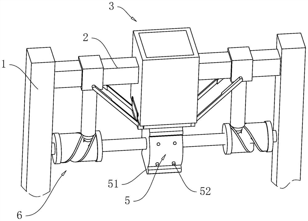
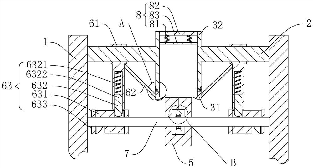
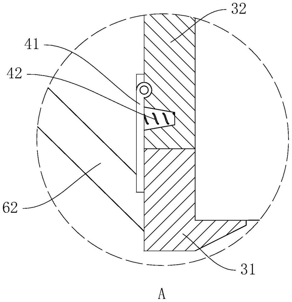
[0038] The embodiment of the present application discloses a multifunctional collating machine, refer to figure 1 and figure 2 , a multifunctional collating machine includes a vertically arranged support frame 1, a fixed shaft 2 with a rectangular cross section is horizontally and fixedly arranged on the support frame 1, and a receiving structure 3 is arranged on the fixed shaft 2, and the receiving structure 3 It includes two L-shaped support sections 31 and a vertically arranged rectangular accommodating box 32. The accommodating box 32 is provided with a rectangular through hole along the vertical direction. The side of the long end is perpendicular to the axis of the fixed shaft 2, the short ends of the two supporting sections 31 are arranged opposite to each other, and the long ends of each supporting section 31 are hinged to the bottom of the accommodating box 32, and ...


PUM


Abstract

The invention relates to the technical field of collating machines, in particular to a multifunctional collating machine which comprises a supporting frame, a fixing shaft is arranged on the supporting frame, a containing structure is arranged on the fixing shaft, the containing structure comprises two L-shaped supporting sections and a containing box, openings are formed in the two opposite sides of the containing box, and the containing box is used for containing paper piles. The two supporting sections are hinged to the same open end of the containing box, the short edge ends of the two supporting sections are oppositely arranged, the long edge ends of the supporting sections are hinged to the containing box, each supporting section is provided with a reset structure, the inward sides of the short edges of the two supporting sections are arranged in a coplanar mode and abut against the bottom of a paper pile, and the paper pile is arranged in the containing box. A page holding roller is arranged right below the paper pile, the page holding roller is rotationally connected to the supporting frame, and a linkage structure is arranged between the page holding roller and the supporting section. The collating machine has the effect of reducing the resistance borne by the paper when the collating machine outputs the paper.

Description

technical field [0001] The present application relates to the technical field of collating machines, in particular to a multifunctional collating machine. Background technique [0002] Collating machine is a device that can match paper of different page numbers together to form a post. It can usually be divided into tower collation machine and horizontal collation machine, and can also be divided into signature collation machine and Sheet-fed collating machines can also be divided into swing arm collating machines and wheel collating machines according to different paper feeding methods. [0003] Most of the existing wheel collating machines use a gripping roller to grip pages, and cooperate with a vertically arranged accommodating box to fill the stack. And through the rotation of the gripping roller, the adsorbed paper is driven out of the paper pile, and then the single paper that has been pulled out is collated through the matched transmission mechanism and collation st...

Claims


Application Information

Patent Timeline
Patent Type & Authority Applications(China)
IPC IPC(8): B65H3/10B65H1/06B42C1/00
CPCB65H3/10B65H1/06B42C1/00B65H2701/1131
Inventor 周锋强
Owner 上海伊诺尔实业集团有限公司
Why Eureka
Try Eureka