Check patentability & draft patents in minutes with Patsnap Eureka AI!

Rotation detection device

A technology of rotation detection and rotation part, which is applied in the directions of measuring devices, electric devices, and electromagnetic/magnetic devices to transmit sensing components, etc., which can solve the problems of voltage reduction and difficulty in improving rotation detection accuracy.

Pending Publication Date: 2022-07-26
HIROSE ELECTRIC GROUP
View PDF2 Cites 0 Cited by
  • Summary
  • Abstract
  • Description
  • Claims
  • Application Information

AI Technical Summary

Problems solved by technology

However, if the size of the magnet or the length of the magnetic wire of each magnetic sensor is shortened, the voltage of the pulse output from the coil will decrease, making it difficult to improve the detection accuracy of rotation.

Method used


Image

  • Rotation detection device
  • Rotation detection device
  • Rotation detection device

Examples


Embodiment Construction

[0030] (rotation detection device)

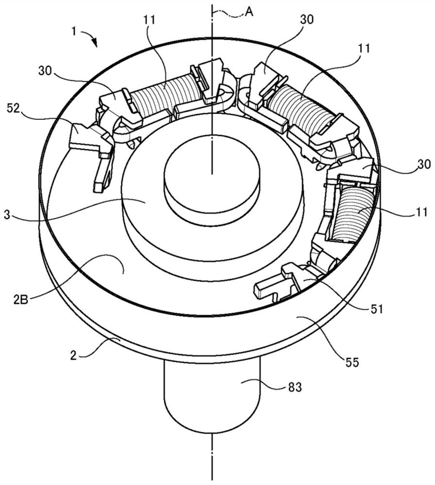
[0031] figure 1 The rotation detection device 1 according to the embodiment of the present invention is shown together with the rotation shaft 83 . figure 2 means from figure 1 The state of the rotation detection device 1 is observed from the upper part of the center. image 3 Indicates that the rotation detection device 1 is moved along the figure 2 Cut off at cut-off line III-III and from figure 2 The state of the section is observed from the bottom of the center.

[0032] The rotation detection device 1 is a device that detects the rotation of an object using the Great Barkhausen effect. In this embodiment, the case where the rotation detection device 1 is applied to the motor 81 is taken as an example. like image 3 As shown, the motor 81 includes a motor body 82 and a rotating shaft 83 . The rotating shaft 83 rotates with respect to the motor body 82 . The motor main body 82 has a mechanism for rotating the rotating shaft 8...


PUM


Abstract

The invention relates to a rotation detection device. The purpose of the present invention is to improve rotation detection accuracy while reducing the size of a rotation detection device provided with a yoke. The rotation detection device includes a magnet rotating together with a rotating shaft, magnetic sensors fixed to a substrate and disposed on an outer peripheral side of the magnet, and a yoke fixed to the substrate and controlling a magnetic flux of a magnetic field formed by the magnet, each magnetic sensor including a magnetic wire, a coil, and a bobbin. Each yoke is provided with a left yoke piece and a right yoke piece that partially cover the left and right portions of the magnetic sensor, the left yoke piece having a left front plate portion that extends linearly from the left portion of the bobbin to the front of the coil from the front of a portion that is on the left side of the portion where the coil is provided, and that is inclined with respect to the extension direction of the magnetic wire, and the right yoke piece having a right front plate portion that is inclined with respect to the extension direction of the coil. The left yoke piece has a left front plate portion formed so that the right end of the left front plate portion is located rearward of the left end of the left front plate portion, and the right yoke piece has a right front plate portion formed in bilateral symmetry with the left front plate portion.

Description

technical field [0001] The present invention relates to a rotation detection device that uses magnetism to detect the rotation of an object. Background technique [0002] As a rotation detection device that detects the rotation of an object using magnetism, the following Patent Document 1 describes a rotation detection device using the Great Barkhausen effect. The basic structure of the rotation detection device using the large Barkhausen effect will be described by taking, as an example, a case where the rotation of the rotation shaft of the motor is detected by the rotation detection device using the large Barkhausen effect. [0003] A rotation detection device utilizing the Great Barkhausen effect includes a magnet and a plurality of magnetic sensors. For example, the magnet is fixed to the rotating shaft, and rotates together with the rotating shaft. Thereby, since the N pole and the S pole of the magnet rotate together with the rotating shaft, a rotating magnetic fiel...

Claims


Application Information

Patent Timeline
Patent Type & Authority Applications(China)
IPC IPC(8): G01D5/245
CPCG01D5/245G01P3/4815G01D5/20G01B7/30
Inventor 江川广祐
Owner HIROSE ELECTRIC GROUP
Features
  • R&D
  • Intellectual Property
  • Life Sciences
  • Materials
  • Tech Scout
  • Unparalleled Data Quality
  • Higher Quality Content
  • 60% Fewer Hallucinations
Learn More