Light-emitting device, display panel and manufacturing method of light-emitting device

A light-emitting device and light-emitting layer technology, which is applied in the production of display panels and light-emitting devices, and in the field of light-emitting devices, can solve problems such as high simultaneous energy level matching, unbalanced hole and electron injection, and difficult to find mobility, etc., to achieve realizability Strong, Highly Practical Effects

Pending Publication Date: 2022-07-26
BOE TECH GRP CO LTD
View PDF0 Cites 0 Cited by
  • Summary
  • Abstract
  • Description
  • Claims
  • Application Information

AI Technical Summary

Problems solved by technology

[0003] The invention provides a light-emitting device, a display panel and a method for making the light-emitting device, so as to improve the problem that it

Method used


Image

  • Light-emitting device, display panel and manufacturing method of light-emitting device
  • Light-emitting device, display panel and manufacturing method of light-emitting device
  • Light-emitting device, display panel and manufacturing method of light-emitting device

Examples


Embodiment Construction

[0040] In order to make the purposes, technical solutions and advantages of the embodiments of the present disclosure more clear, the technical solutions of the embodiments of the present disclosure will be clearly and completely described below with reference to the accompanying drawings of the embodiments of the present disclosure. Obviously, the described embodiments are some, but not all, embodiments of the present disclosure. Based on the described embodiments of the present disclosure, all other embodiments obtained by those of ordinary skill in the art without creative efforts fall within the protection scope of the present disclosure.

[0041] Unless otherwise defined, technical or scientific terms used in this disclosure shall have the ordinary meaning as understood by one of ordinary skill in the art to which this disclosure belongs. As used in this disclosure, "first," "second," and similar terms do not denote any order, quantity, or importance, but are merely used ...


PUM


Abstract

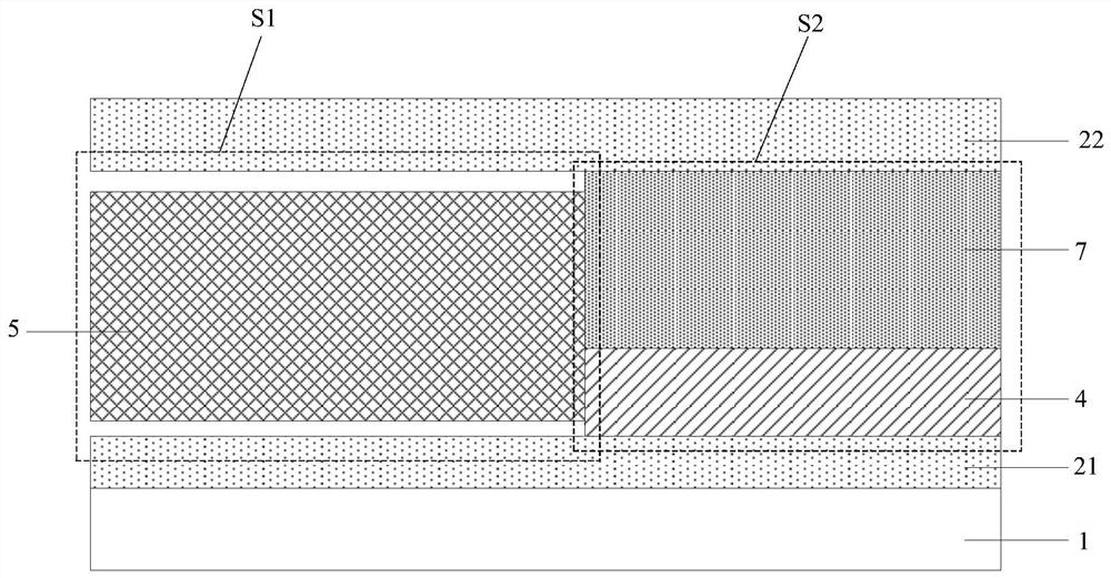
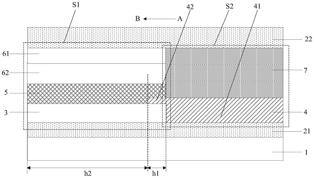
The invention discloses a light-emitting device, a display panel and a manufacturing method of the light-emitting device, and aims to solve the problems that materials which are high in mobility and matched in energy level are difficult to find at present, and injection of holes and electrons is unbalanced. The light-emitting device comprises a light-emitting area and a regulation and control area which are located between the first electrode layer and the second electrode layer. The light-emitting region includes: a light-emitting layer; for the light-emitting region, one of the first electrode layer and the second electrode layer, which has a small number of carriers injected into the light-emitting layer in unit time, is used as a minority carrier injection electrode layer, and the other one is used as a multi-carrier injection electrode layer; the regulation and control region comprises an insulating layer and a carrier transport layer which are arranged in a laminated manner; the carrier transport layer is in contact with the minority carrier injection electrode layer, the insulating layer is in contact with the multi-carrier injection electrode layer, and the side wall of the carrier transport layer is in contact with the side wall of the light-emitting layer.

Description

technical field [0001] The present invention relates to the technical field of semiconductors, and in particular, to a light-emitting device, a display panel and a method for manufacturing the light-emitting device. Background technique [0002] For quantum dot light-emitting devices, the balance of electron and hole injection is one of the keys to achieve high-efficiency and long-life devices. The current quantum dot light-emitting devices can be divided into two types according to the structure of electrons and holes. For devices with many electrons, the usual solution is to improve the injection of holes, such as selecting materials with higher hole mobility and more matched energy levels. Devices in which holes are many electrons increase electron injection in the same way. However, the current practical problem in quantum dot devices is that it is difficult to find materials with high mobility and matching energy levels, and there is still the problem of unbalanced in...

Claims


Application Information

Patent Timeline
IPC IPC(8): H01L51/50H01L51/52H01L51/56H01L27/32
CPCH10K59/10H10K50/15H10K50/16H10K50/844H10K71/00
Inventor 卢志高
Owner BOE TECH GRP CO LTD
Why Eureka
Try Eureka