Supercharge Your Innovation With Domain-Expert AI Agents!

Radiography imaging examination device for radiology department

A technology of contrast imaging and inspection equipment, applied in the field of medical equipment, to achieve the effects of avoiding tilt instability, low cost, and convenient delivery of bed boards

Inactive Publication Date: 2022-07-29
商丘市第一人民医院
View PDF1 Cites 2 Cited by
  • Summary
  • Abstract
  • Description
  • Claims
  • Application Information

AI Technical Summary

Problems solved by technology

[0005] The purpose of the present invention is to provide a radiographic imaging inspection device to solve the problems such as the defects of the prior art proposed in the above-mentioned background technology

Method used


Image

  • Radiography imaging examination device for radiology department
  • Radiography imaging examination device for radiology department
  • Radiography imaging examination device for radiology department

Examples


Embodiment 1

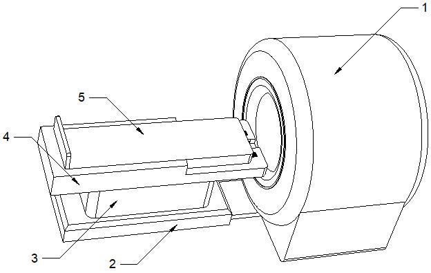
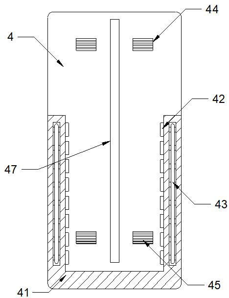
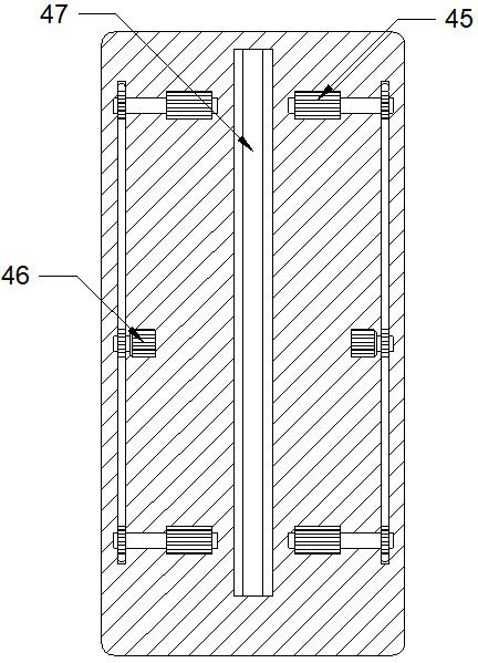
[0025] see Figures 1 to 6 , In the embodiment of the present invention, a radiographic imaging inspection device includes a main body 1 of a detection device and a bed frame 4, the main body 1 of the detection device is a commonly used inspection device in the prior art, and the bed frame 4 is relatively arranged on the detection device On one side of the opening of the main body 1, a base plate 2 is installed on one side of the main body 1 of the detection equipment, and a support cover 3 is fixedly connected on the base plate 2, and a bed frame 4 is installed on the support cover 3 through a rotating adjustment mechanism, so The bed frame 4 is slidably assembled and connected with a bed board 5 , a guide driving mechanism for driving the bed board 5 to move relative to the main body 1 of the detection device is arranged in the bed frame 4 , and a sliding limit with the bed board 5 is installed on the bed frame 4 . A matching guide mechanism, the guide mechanism and the guid...

Embodiment 2

[0033] see figure 1 and 6 , In the embodiment of the present invention, the end of the support cover 3 facing the bed frame 4 is embedded with an accommodating cavity 31, and the rotation adjustment mechanism includes a mounting plate 32 that is rotatably connected above the accommodating cavity 31 through a hinge. 32 is flush with the surface of the support cover 3, the bed frame 4 is assembled and connected to the mounting plate 32, the two sides of the accommodating cavity 31 are symmetrically and fixedly connected with guide strips 34, and the two sets of guide strips 34 are slidingly fitted with guide strips 34. An inner rack 33 , one end of the inner rack 33 is fixedly connected to the mounting plate 32 . Preferably, both the inner rack 33 and the guide bar 34 are arranged in an arc shape, the circle centers of the inner rack 33 and the guide bar 34 coincide with the hinge rotation axis at the end of the mounting plate 32, and the accommodating cavity 31 is rotatably co...


PUM


Abstract

The invention relates to the technical field of medical instruments, and discloses a radiology department radiography imaging examination device which comprises an examination equipment main body and a bed frame, the bed frame is oppositely arranged on one side of an opening of the examination equipment main body, a bottom plate is installed on one side of the examination equipment main body, and a supporting cover is fixedly connected to the bottom plate; a bed frame is installed on the supporting cover through a rotation adjusting mechanism, a bed plate is slidably assembled and connected to the bed frame, a guide driving mechanism for driving the bed plate to move relative to the detection equipment body is arranged in the bed frame, and a guide mechanism in sliding limiting fit with the bed plate is installed on the bed frame; the guide mechanism and the guide driving mechanism are arranged in a synchronous reverse transmission mode. Patients having difficulty in moving can lean against the bed board conveniently, the bed frame and the bed board are driven to rotate by rotating the adjusting mechanism, examination of the patients is facilitated, the bed board can be conveniently guided and conveyed, the guide mechanism can limit the bed board, the bed board is prevented from inclining and being unstable, and the patients can be placed more stably.

Description

technical field [0001] The invention relates to the technical field of medical devices, in particular to a radiography imaging examination device. Background technique [0002] In the construction of modern hospitals, the radiology department is a department integrating inspection, diagnosis and treatment. Many diseases in clinical departments must be checked by radiology equipment to achieve definite diagnosis and auxiliary diagnosis. With the development of electronic computer technology, modern physics, electronic The organic combination of science and traditional radiology has enabled modern radiology to be equipped with high-tech wings. Radiology has shown new vitality in the medical field, and its status in diagnosis and treatment is becoming more and more irreplaceable. [0003] Chinese Patent Publication No. CN211834428U An intelligent angiography auxiliary inspection imaging device for radiology department includes an angiography imaging main body, a support table i...

Claims


Application Information

Patent Timeline
Patent Type & Authority Applications(China)
IPC IPC(8): A61B6/04A61B6/00
CPCA61B6/0407A61B6/481
Inventor 李玉舟
Owner 商丘市第一人民医院
Features
  • R&D
  • Intellectual Property
  • Life Sciences
  • Materials
  • Tech Scout
  • Unparalleled Data Quality
  • Higher Quality Content
  • 60% Fewer Hallucinations
Learn More