Catalytic waste gas treatment device for multi-bin waste gas treatment process

A waste gas treatment device and waste gas treatment technology, which is applied in the direction of combined device, water/sewage treatment, water/sludge/sewage treatment, etc., can solve the problems of affecting the efficiency of waste gas treatment and the deterioration of activated carbon adsorption effect, so as to reduce labor intensity , improve the utilization rate, improve the effect of processing efficiency

Pending Publication Date: 2022-07-29
江苏爱尚环境科技有限公司
View PDF8 Cites 2 Cited by
  • Summary
  • Abstract
  • Description
  • Claims
  • Application Information

AI Technical Summary

Problems solved by technology

[0003] However, in the existing multi-chamber exhaust gas treatment process, the catalytic exhaust gas treatment device usually directly passes the exhaust gas into multiple activated carbon filter chambers for filtration after spraying treatment in the spray tower, such as a patented multi-chamber exhaust gas Treatment process Catalytic exhaust gas treatment equipment (notice number: CN210278719U), the exhaust gas sprayed by the spray tower is directly passed into multiple activated carbon filter chambers for purification and adsorption, because the exhaust gas will still have dust after spraying treatment , and there will be a large amount of water vapor, which will be directly passed into the activated carbon filter chamber for filtration, resulting in poor adsorption effect of activated carbon in the activated carbon filter chamber, so that the activated carbon in the activated carbon filter chamber needs to be frequently regenerated, affecting the efficiency of waste gas treatment

Method used


Image

  • Catalytic waste gas treatment device for multi-bin waste gas treatment process
  • Catalytic waste gas treatment device for multi-bin waste gas treatment process
  • Catalytic waste gas treatment device for multi-bin waste gas treatment process

Examples


Embodiment Construction

[0026] The preferred embodiments of the present invention will be described below with reference to the accompanying drawings. It should be understood that the preferred embodiments described herein are only used to illustrate and explain the present invention, but not to limit the present invention.

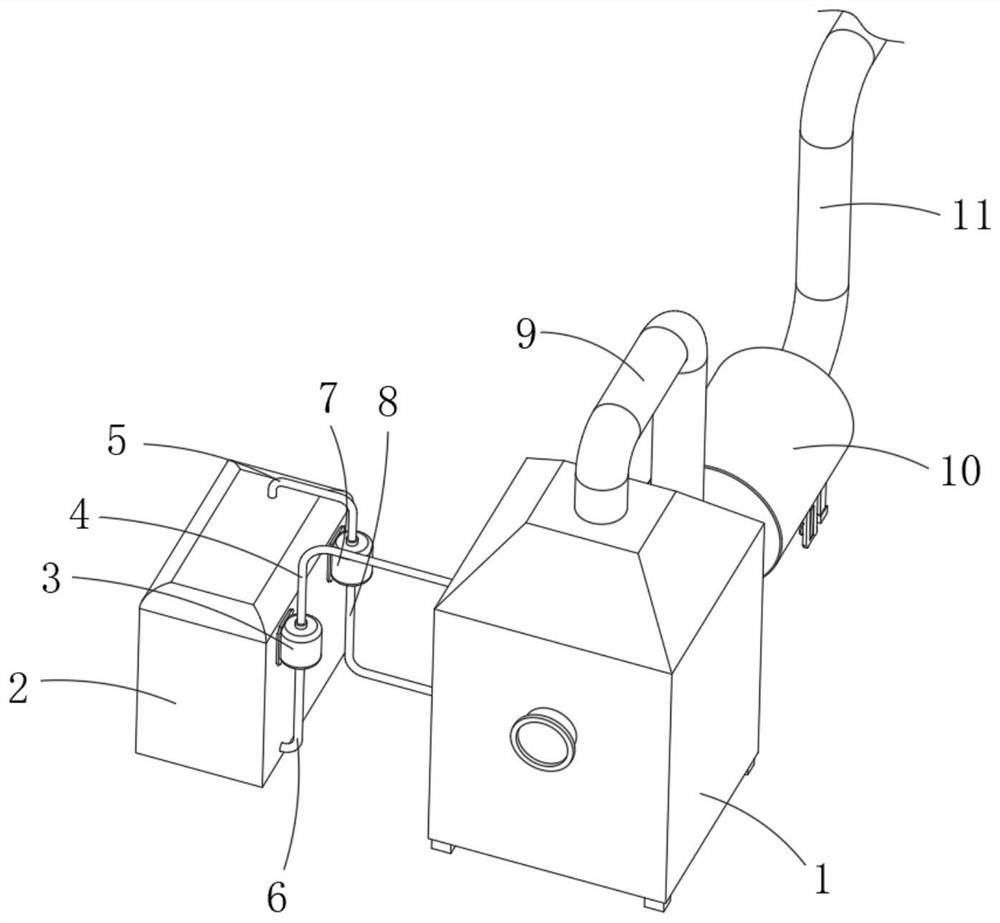
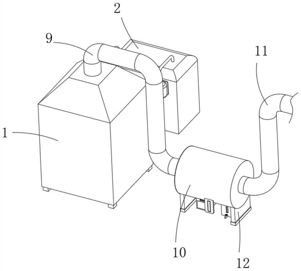
[0027] see Figures 1 to 5 , In the embodiment of the present invention, a multi-silo type waste gas treatment process catalytic waste gas treatment device includes a spray tower 1, a water circulation mechanism, a preliminary purification mechanism, a self-cleaning mechanism and a storage mechanism, and the spray tower 1 is connected with a water circulation mechanism Mechanism, the air outlet of the spray tower 1 is communicated with a preliminary purification mechanism, and the preliminary purification mechanism includes a purification cylinder 10, an air pipe 9, a support block 12, a dust filter 25 and a ceramic filter plate 27, a drainage pipe 22 and a ventilation pipe 11 O...


PUM


Abstract

The invention discloses a multi-bin waste gas treatment process catalytic waste gas treatment device, and relates to the technical field of waste gas treatment.The multi-bin waste gas treatment process catalytic waste gas treatment device comprises a spray tower, a water circulation mechanism, a primary purification mechanism, a self-cleaning mechanism and a storage mechanism, the spray tower is connected with a water circulation machine, and a gas outlet of the spray tower communicates with the primary purification mechanism; the primary purification mechanism comprises a purification barrel, a gas conveying pipe, a supporting block, a dustproof net, a ceramic filter plate, a drainage pipe and a ventilation pipe, the purification barrel is arranged on one side face of the spraying tower, and a gas outlet of the spraying tower is fixedly communicated with the side face of the purification barrel through the gas conveying pipe. The waste gas treatment device has the advantages that frequent shutdown for regeneration of activated carbon is avoided, the waste gas treatment efficiency is improved, automatic cleaning can be realized in the use process, the labor intensity of workers is reduced, shutdown for cleaning is not needed, and the waste gas purification treatment efficiency is further improved.

Description

technical field [0001] The invention relates to the technical field of exhaust gas treatment, in particular to a multi-chamber exhaust gas treatment process catalytic exhaust gas treatment device. Background technique [0002] Multi-silo type waste gas treatment process catalytic waste gas treatment equipment, usually used through spray towers, activated carbon filter chambers and catalytic combustion chambers, through multiple activated carbon filter chambers to adsorb and purify exhaust gas, and use hot air to desorb organic matter from activated carbon When the concentration of organic waste gas reaches 200mg / m3 or more, the organic waste gas can maintain spontaneous combustion in the catalytic bed without external heating, which can meet the combustion requirements. And the heat required for adsorption to achieve the purpose of energy saving. [0003] However, the existing multi-chamber exhaust gas treatment process catalytic exhaust gas treatment device usually directl...

Claims


Application Information

Patent Timeline
Patent Type & Authority Applications(China)
IPC IPC(8): B01D50/60B01D53/26B01D53/04B01D46/681C02F1/461
CPCB01D50/60B01D53/266B01D53/04B01D46/681C02F1/46104B01D2253/102
Inventor 董良飞
Owner 江苏爱尚环境科技有限公司
Why Eureka
Try Eureka