Laser cutting device capable of rapidly cutting floor

A laser cutting and fast cutting technology, applied in laser welding equipment, metal processing equipment, welding equipment and other directions, can solve the problems of low floor accuracy and efficiency, and achieve the effect of ensuring accuracy, efficiency and stability

Inactive Publication Date: 2022-07-29
江苏中邦木业有限公司
View PDF6 Cites 0 Cited by
  • Summary
  • Abstract
  • Description
  • Claims
  • Application Information

AI Technical Summary

Problems solved by technology

[0003] In order to solve the problem of low precision and efficiency of floor cutting in the use of the above-mentioned general floor laser cutting device, and achieve the above purpose of reliably and effectively ensuring the precision and efficiency of floor cutting, the present invention is realized through the following technical solutions: A laser cutting device capable of rapidly cutting floors, comprising a base, a positioning plate is slidably connected to the right wall of the inner cavity of the base, a screw is threadedly connected to the right end of the positioning plate, and an elastic strip is slidably connected to the surface of the positioning plate. A cutting mechanism is movably connected to the inner wall on the left side of the base, and the cutting mechanism includes a straight guide groove. The right side of the straight guide groove is evenly connected with a metal strip. The left wall of the inner cavity of the base is slidably connected to an elastic telescopic rod. The right side of the rod is fixedly connected with a laser cutting rod, the left end of the laser cutting rod is rotatably connected with a guide roller, the front end of the base is slidably connected with a sliding beam, the rear end of the sliding beam is slidably connected with a laser measuring rod, and the left end of the laser measuring rod Rotationally connected with electromagnetic roller

Method used


Image

  • Laser cutting device capable of rapidly cutting floor
  • Laser cutting device capable of rapidly cutting floor
  • Laser cutting device capable of rapidly cutting floor

Examples


Embodiment Construction

[0020] The technical solutions in the embodiments of the present invention will be clearly and completely described below with reference to the accompanying drawings in the embodiments of the present invention. Obviously, the described embodiments are only a part of the embodiments of the present invention, but not all of the embodiments. Based on the embodiments of the present invention, all other embodiments obtained by those of ordinary skill in the art without creative efforts shall fall within the protection scope of the present invention.

[0021] Examples of the laser cutting device that can quickly cut floors are as follows:

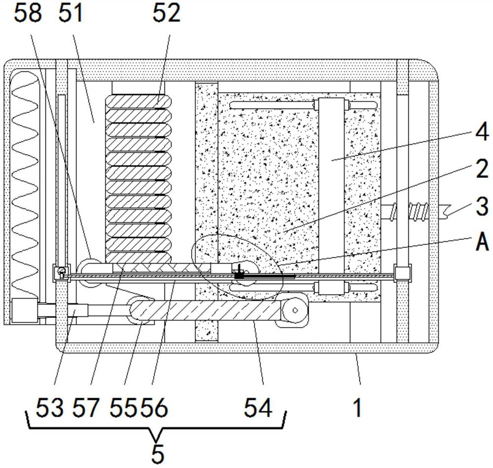
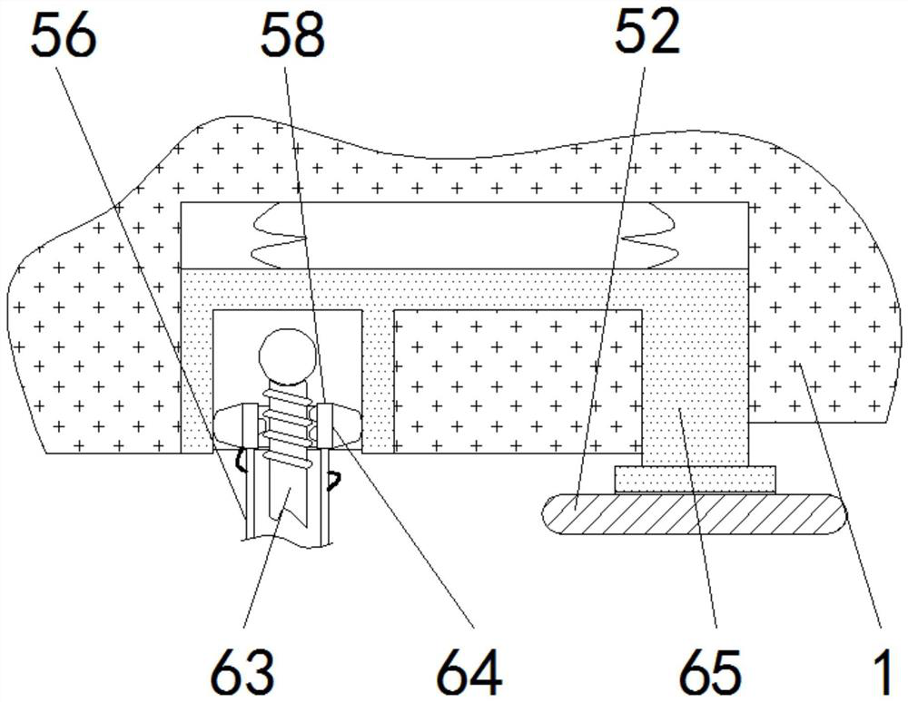
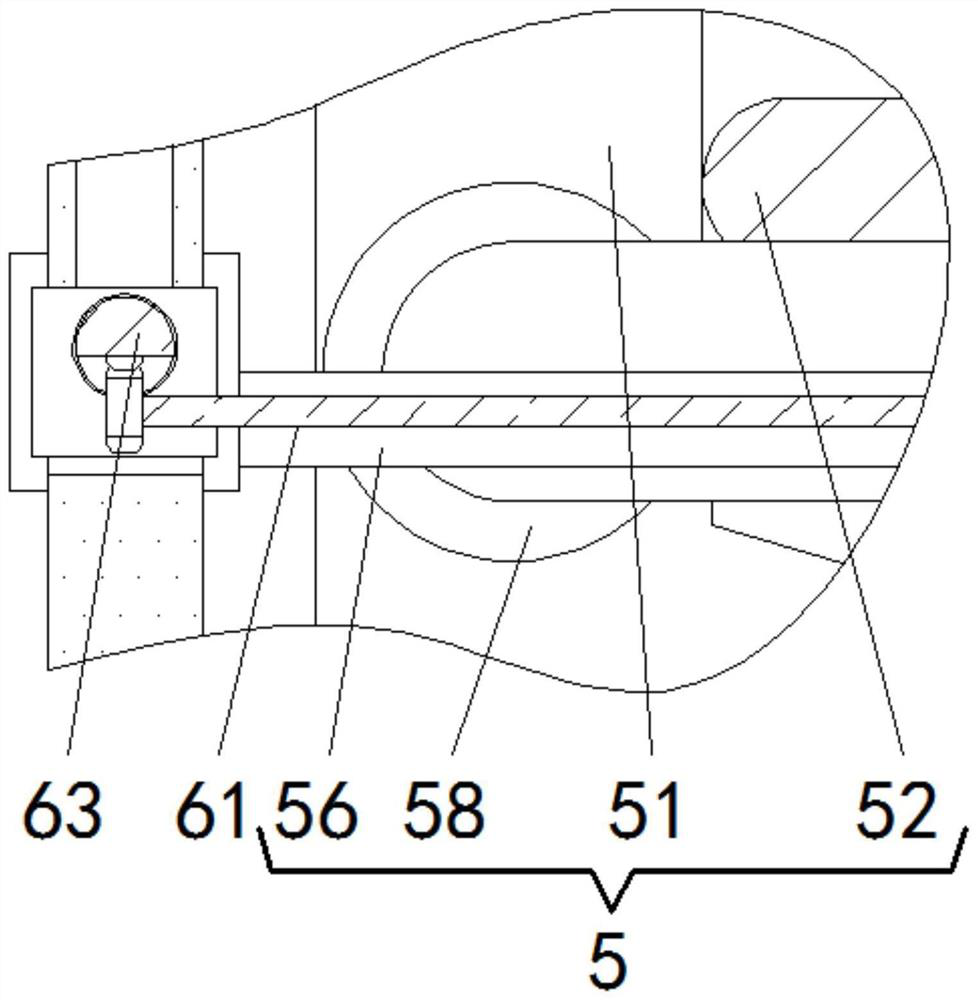
[0022] see Figure 1-Figure 5 , a laser cutting device that can quickly cut the floor, including a base 1, a positioning plate 2 is slidably connected to the right wall of the inner cavity of the base 1, a screw 3 is threadedly connected to the right end of the positioning plate 2, and the screw 3 is rotatably connected to the right wall of the b...


PUM


Abstract

The invention relates to the technical field of laser cutting, and discloses a laser cutting device capable of quickly cutting floors, which comprises a base, a positioning plate is slidably connected to the right wall of an inner cavity of the base, a screw rod is in threaded connection to the right end of the positioning plate, an elastic strip is slidably connected to the surface of the positioning plate, and a cutting mechanism is movably connected to the inner wall of the left side of the base. The cutting mechanism comprises a straight guide groove, metal strips are evenly connected to the right side of the straight guide groove, an elastic telescopic rod is slidably connected to the left wall of an inner cavity of the base, a laser cutting rod is fixedly connected to the right side of the elastic telescopic rod, a guide connecting roller is rotatably connected to the left end of the laser cutting rod, and a sliding beam is slidably connected to the front end of the base. According to the laser cutting device capable of rapidly cutting the floor, the laser measuring rod is used for being matched with the multiple metal strips to measure and limit the cutting path in advance, then the laser cutting rod is used for conducting secondary advancing and rapid cutting, and therefore the floor cutting precision and efficiency are reliably and effectively guaranteed.

Description

technical field [0001] The invention relates to the technical field of laser cutting, in particular to a laser cutting device capable of rapidly cutting floors. Background technique [0002] At present, the use of laser rapid prototyping technology can achieve efficient cutting of the required shape of the corresponding material. When decorating and laying the floor in the room, a small amount of floor needs to be cut into a shape suitable for special areas such as walls. In order to quickly complete the cutting For the cutting operation, a small laser cutting device can be used for cutting, but the traditional laser cutting device needs to manually control the cutting route due to cost constraints. And it is difficult to limit the route of the laser device, so directly operating the laser device for cutting, under the guidance of the operation error, it is easy to make the real-time cutting area and the scribing area deviate, and the synchronization of manual comparison and...

Claims


Application Information

Patent Timeline
Patent Type & Authority Applications(China)
IPC IPC(8): B23K26/08B23K26/38B23K26/70
CPCB23K26/38B23K26/0869B23K26/702
Inventor 肖立霞
Owner 江苏中邦木业有限公司
Why Eureka
Try Eureka