
Rotary bottle blowing machine

A bottle blowing machine and bottle blowing cavity technology, which is applied to household appliances, hollow items, other household appliances, etc., can solve the problems of long time consumption, reduced production efficiency, cumbersome sterilization and disinfection steps, etc., and achieves convenient and simple operation and improves work efficiency. , to ensure the effect of moving

Pending Publication Date: 2022-07-29
HANGZHOU ZHONGYA MACHINERY CO LTD
View PDF0 Cites 0 Cited by
  • Summary
  • Abstract
  • Description
  • Claims
  • Application Information

AI Technical Summary

Problems solved by technology

[0002] At present, the working process of the blow molding machine with filling function on the market is as follows. First, the bottle is prepared by the blowing mechanism, and then the bottle is sent to the filling mechanism for filling. In order to ensure the cleanliness of the blow molding machine, it is usually necessary to After the blow molding machine has been working for a period of time, the blow molding machine is stopped for sterilization and disinfection. Because the sterilization and disinfection requirements of the filling mechanism and the blowing mechanism are different, the sterilization and disinfection steps of the existing blow molding machine are relatively cumbersome and time-consuming. long, reducing productivity

Method used


Image

  • Rotary bottle blowing machine
  • Rotary bottle blowing machine
  • Rotary bottle blowing machine

Examples


Embodiment 1

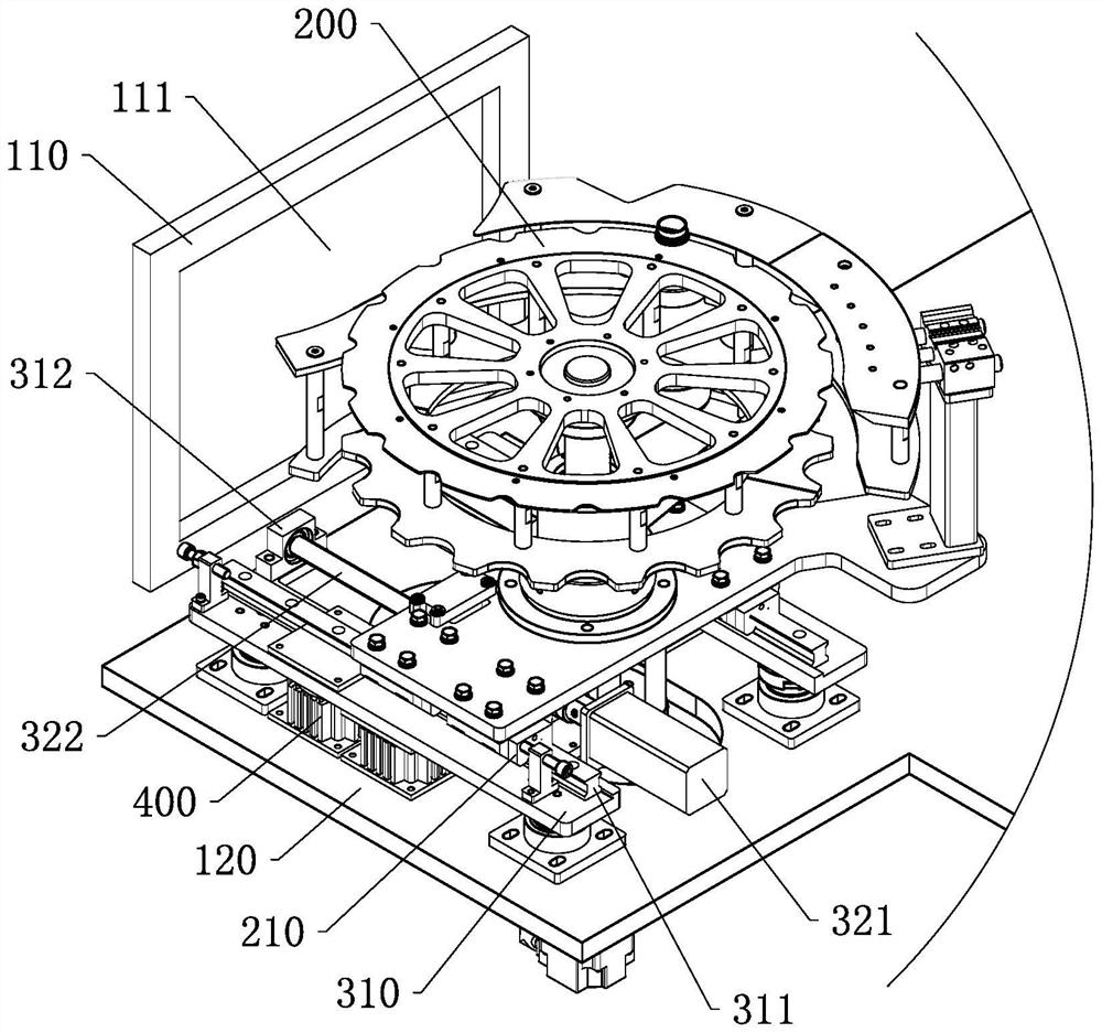
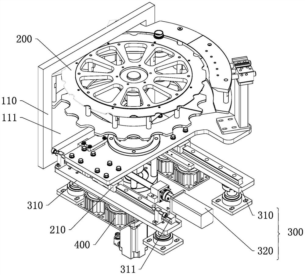
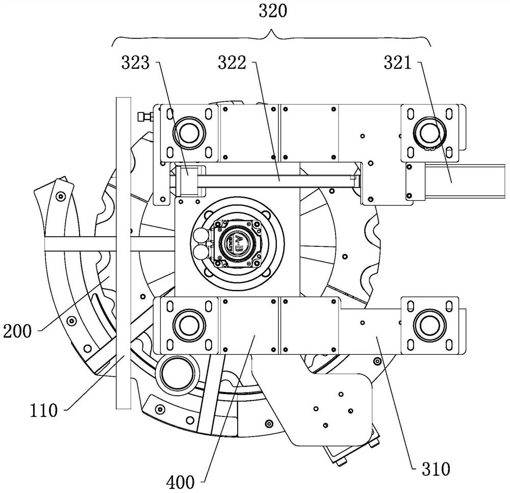
[0038] A rotary blow molding machine, such as Figure 1 to Figure 3 As shown, it includes a casing. A baffle 110 is vertically arranged in the casing. The baffle 110 divides the interior of the casing into a filling cavity and a blowing cavity arranged side by side. The blowing cavity is used to accommodate the blowing mechanism. The filling cavity is used to accommodate the filling mechanism, and the interior of the casing is separated by setting the baffle 110 to meet the different sterilization requirements of the filling cavity and the blowing cavity. A transition wheel 200 and a lifting and translation device for driving the transition wheel 200 to lift and translate are arranged in the blowing cavity. The transition wheel 200 is connected to the upper part of the lifting and translation device, and the baffle 110 is provided with a connection between the filling cavity and the blowing. The through hole 111 of the cavity, the transfer wheel 200 can pass through the through ...

Embodiment 2

[0046] The difference between this embodiment and the first embodiment is that, in this embodiment, the linear driving mechanism is a driving cylinder, the driving cylinder is fixed on the mounting seat, and the output shaft of the driving cylinder is horizontally arranged and connected to the bottom of the transition wheel disc, It is used to push the transition wheel to translate, and the output force of the cylinder is larger, and as a linear drive mechanism, the driving effect of the heavy transition wheel is better. Of course, it can be understood that the linear drive mechanism in this embodiment can also be an electric push rod.


PUM


Abstract

The invention discloses a rotary bottle blowing machine which comprises a machine shell, a baffle is arranged in the machine shell and divides the interior of the machine shell into a filling cavity and a bottle blowing cavity, a through hole is formed in the baffle, a lifting translation device and a transition wheel disc are arranged in the bottle blowing cavity, and the transition wheel disc has a working position and a sterilization position. The transition wheel disc is completely positioned in the bottle blowing cavity; when the transition wheel disc is in the working position, the transition wheel disc partially extends into the through hole, and the lifting and translation device drives the transition wheel disc to lift and translate so as to switch between the working position and the sterilization position. According to the rotary bottle blowing machine, different sterilization and disinfection requirements of the bottle blowing mechanism and the filling mechanism are met through the arrangement of the baffles, conveying of packaging bottles among different mechanisms in the working state is met through the through holes and the lifting translation device for driving the transition wheel disc, and the rotary bottle blowing machine can be conveniently and rapidly switched between the working state and the shutdown state for sterilization and disinfection; operation is convenient and simple, and working efficiency of the machine is improved.

Description

technical field [0001] The invention specifically relates to a rotary bottle blowing machine. Background technique [0002] At present, the working process of the bottle blowing machine with filling function on the market is as follows. First, the bottle is prepared by the bottle blowing mechanism, and then the bottle is transferred to the filling mechanism for filling. In order to ensure the cleanliness of the blow molding machine, it is usually necessary to After the bottle blowing machine has been working for a period of time, the bottle blowing machine is stopped for sterilization and disinfection. Because the sterilization and disinfection requirements of the filling mechanism and the bottle blowing mechanism are different, the sterilization and disinfection steps of the existing bottle blowing machine are complicated and time-consuming. long, reducing production efficiency. SUMMARY OF THE INVENTION [0003] The technical problem to be solved by the present invention...

Claims


Application Information

Patent Timeline
Patent Type & Authority Applications(China)
IPC IPC(8): B29C49/42B29C49/46B29L22/00
CPCB29C49/42B29C49/4273B29C49/46B29L2022/00
Inventor 史中伟史正刘普锋
Owner HANGZHOU ZHONGYA MACHINERY CO LTD
Learn More