
Air-ground amphibious detector, detection platform and detection method

A detector, land and air technology, applied in the field of land and air amphibious detectors, can solve the problems of large space occupied by rotors, limited detection environment, large space occupied by land and air amphibious detectors, etc. The effect of reducing the risk of getting stuck

Pending Publication Date: 2022-07-29
BEIJING INSTITUTE OF TECHNOLOGYGY +1
View PDF0 Cites 0 Cited by
  • Summary
  • Abstract
  • Description
  • Claims
  • Application Information

AI Technical Summary

Problems solved by technology

[0002] At present, most detectors still use a single form of carrier such as unmanned aerial vehicles or unmanned vehicles. The single form of carrier makes the detector only detect in the air or on land, and the applicable detection environment is limited;
[0003] Some detectors can be land-air amphibious, and land-air amphibious detectors can perform vertical take-off and landing, hovering in the air and driving on land, which expands the detection environment of land-air amphibious detectors, but the land-air amphibious detectors in the prior art It is a simple combination of an unmanned vehicle and a UAV, and most UAVs use a rotor structure, which occupies a large space. Correspondingly, the land-air amphibious detector occupies a relatively large space, which makes it suitable for land detection. Under the environment conditions, it is impossible to detect the internal conditions of the small space, and there is a risk of land and air amphibious detectors being stuck in the small space, reducing the recovery rate of land and air amphibious detectors

Method used


Image

  • Air-ground amphibious detector, detection platform and detection method
  • Air-ground amphibious detector, detection platform and detection method
  • Air-ground amphibious detector, detection platform and detection method

Examples


Embodiment Construction

[0065] The present application will be further described in detail below with reference to the accompanying drawings and embodiments. It should be understood that the specific embodiments described herein are only used to explain the related application, but not to limit the application. The described embodiments are only some of the embodiments of the present application, but not all of the embodiments. Based on the embodiments in the present application, all other embodiments obtained by those of ordinary skill in the art without creative efforts shall fall within the protection scope of the present application.

[0066] It should be noted that, for the convenience of description, only the parts related to the relevant application are shown in the drawings. The embodiments in this application and the features in the embodiments may be combined with each other without conflict.

[0067] It should be understood that "system", "device", "unit" and / or "module" as used in this ...


PUM


Abstract

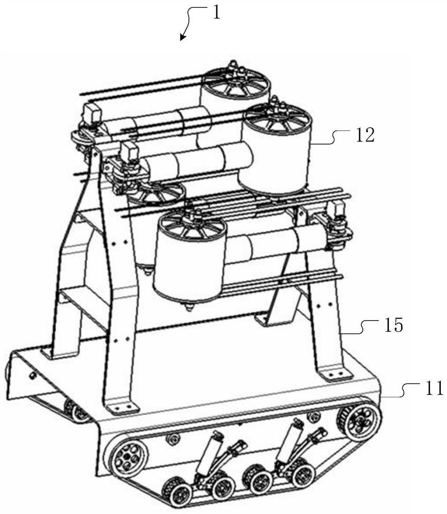
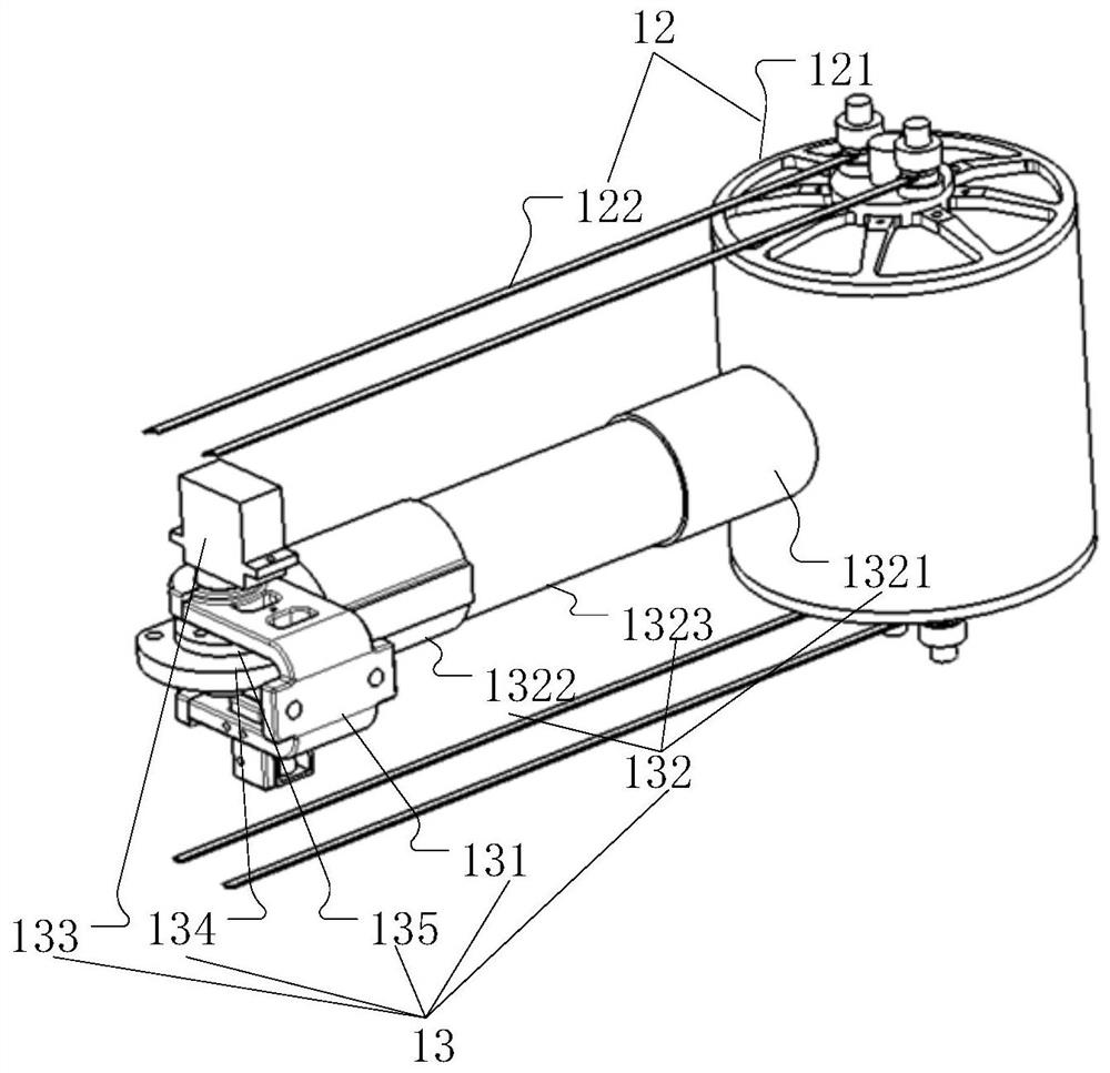
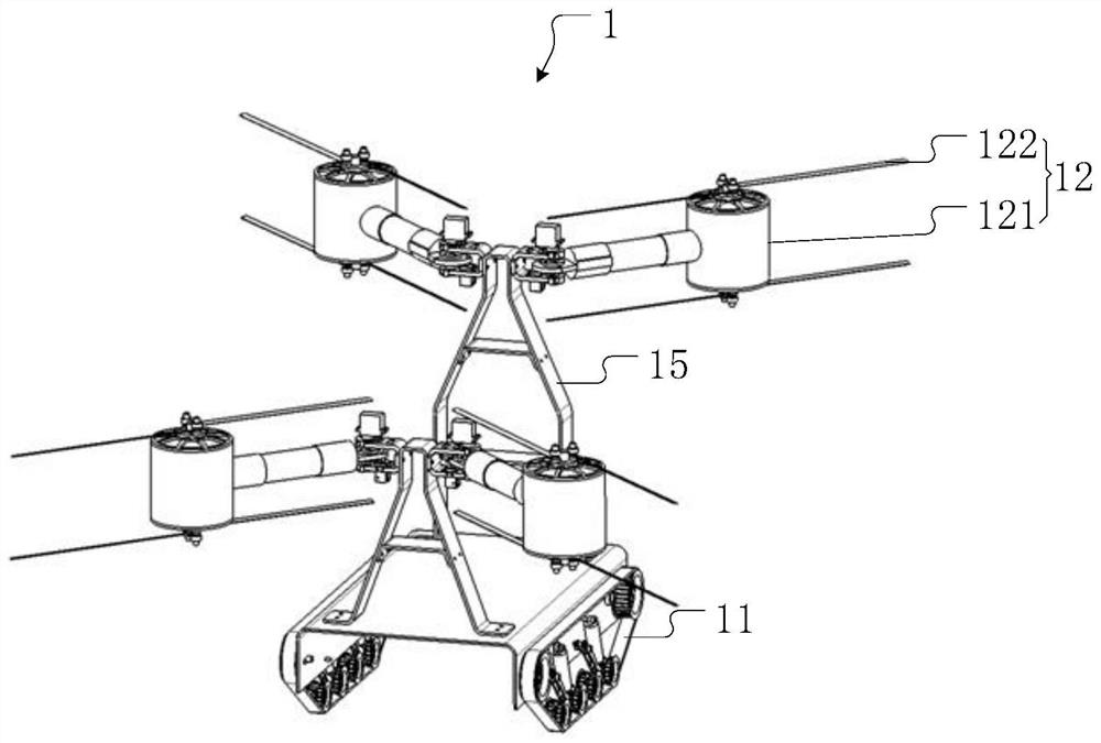
The embodiment of the invention discloses an air-ground amphibious detector, a detection platform and a detection method, and the air-ground amphibious detector comprises a land traveling mechanism and a flying mechanism. When a land detection mode is adopted, the flying mechanism is folded on the land traveling mechanism through a machine arm base, a connecting arm and a first driving part of the folding mechanism, and blades of the flying mechanism are folded side by side in the traveling direction of the land traveling mechanism through a second driving part. The space, occupied by the land-air amphibious detector in the land detection mode, in the running direction of the land running mechanism is reduced, so that the land-air amphibious detector can enter the narrow space of the land and can run in the narrow space, the internal situation of the narrow space is detected, useful information is obtained, and the detection efficiency is improved. The detection environment of the land-air amphibious detector is further expanded, meanwhile, due to the fact that the land-air amphibious detector occupies a small space in the land detection mode, the risk that the land-air amphibious detector is stuck is reduced, and the recovery rate of the land-air amphibious detector cannot be reduced.

Description

technical field [0001] The present application relates to the technical field of detection equipment, in particular to a land-air amphibious detector, a detection platform and a detection method. Background technique [0002] At present, most detectors still use a single form of carrier, such as unmanned aerial vehicle or unmanned vehicle. The single form of carrier makes the detector only detect in the air or on land, and the applicable detection environment is limited; [0003] Some detectors can be land-air amphibious, and land-air amphibious detectors can perform vertical take-off and landing, aerial hovering and land driving, which expands the detection environment of land-air amphibious detectors, but the existing land-air amphibious detectors It is a simple combination of unmanned vehicles and UAVs, and UAVs mostly use rotor structures, and the rotors occupy a large space. Correspondingly, the space occupied by land and air amphibious detectors is also relatively larg...

Claims


Application Information

Patent Timeline
IPC IPC(8): B60F5/02B64C1/06B64C1/30B62D55/06
CPCB60F5/02B64C1/063B64C1/30B62D55/06
Inventor 张旺旺郭彦铭徐彬樊伟刘春桃
Owner BEIJING INSTITUTE OF TECHNOLOGYGY
Learn More